Image display apparatus

a technology of image display and display tube, which is applied in the manufacture of electric discharge tube/lamp, tubes with screens, discharge tubes luminescnet screens, etc., can solve the problems of reducing the amount of electron emission, hindering the display of bright images, and adversely affecting the effect of electron sources

Inactive Publication Date: 2006-03-02
CANON KK
View PDF16 Cites 13 Cited by
  • Summary
  • Abstract
  • Description
  • Claims
  • Application Information

AI Technical Summary

Benefits of technology

[0008] The present invention is designed with respect to such problems, and is directed at providing an image display apparatus with the use of an ion pump, which reduces an influence of a magnetic field, has little nonuniformity in brightness in an image-forming region and hardly causes the change of the brightness with time, and at a manufacturing method therefor.

Problems solved by technology

This is because when a gas is generated in the vacuum chamber and the pressure increases, the gas adversely exerts an adverse effect on the electron sources to decrease an electron emission amount and hinder the display of a bright image, though the extent of the effect depends on the types of the gas.
Gases generated from image display members accumulate in the vicinity of an electron source before reaching a getter installed outside an image display area, locally increase pressure and deteriorate the electron source, which is a peculiar problem particularly to a flat panel display.
The positive ions further may discharge inside the vacuum chamber and damage an apparatus.
However, the planar display needs a strong magnet, and then a magnetic field deflects an electron orbit of the display and may affect images.

Method used


Image

  • Image display apparatus
  • Image display apparatus
  • Image display apparatus

Examples


embodiment 1

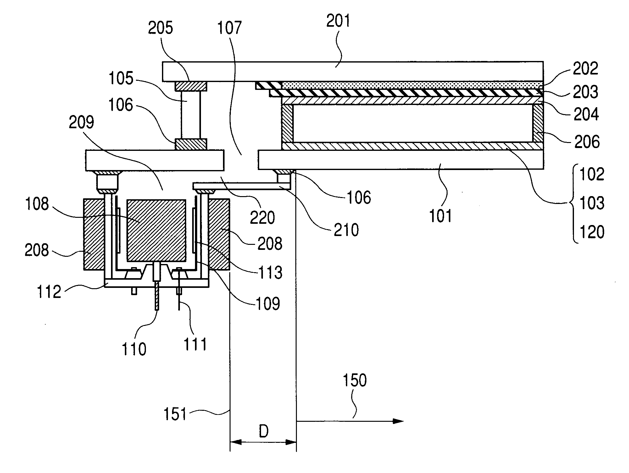
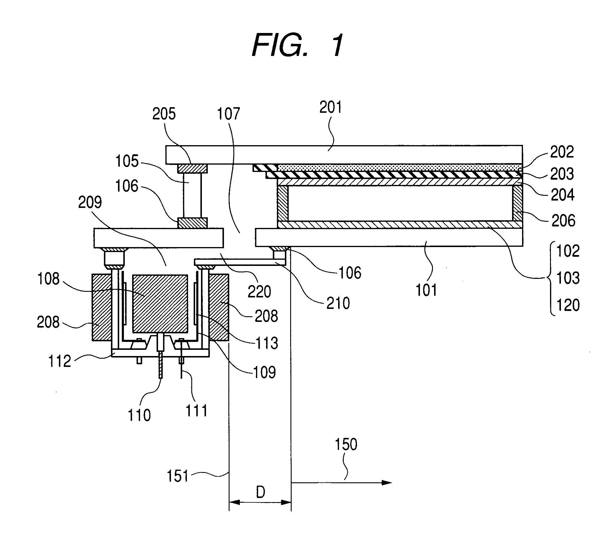
[0091] An image display apparatus having a magnet 208 of an ion pump 209 installed at a position apart from an electron-emitting device 120 (an electron source) and a phosphor film 202 to be exposed to electron beams will be explained with reference to FIG. 1, and a method of producing a vacuum chamber of the image display apparatus, with reference to FIGS. 2 to 7.

[0092] First of all, a method for producing a sealed vessel of an image display apparatus will be described. Soda glass (SL: product made by Nippon Sheet Glass Co., Ltd.) with a thickness of 2.8 mm and a size of 190×270 mm was used for a face plate 201, and the same soda glass with a thickness of 2.8 mm and a size of 240×320 mm was used for a rear plate 101. In the practically used rear plate 101, an outlet 107 with a diameter of 8 mm was opened at a position outside an image region and on the inside of a glass frame 105.

[0093] The film of element electrodes 402 and 403 in a surface conduction type electron-emitting devi...

embodiment 2

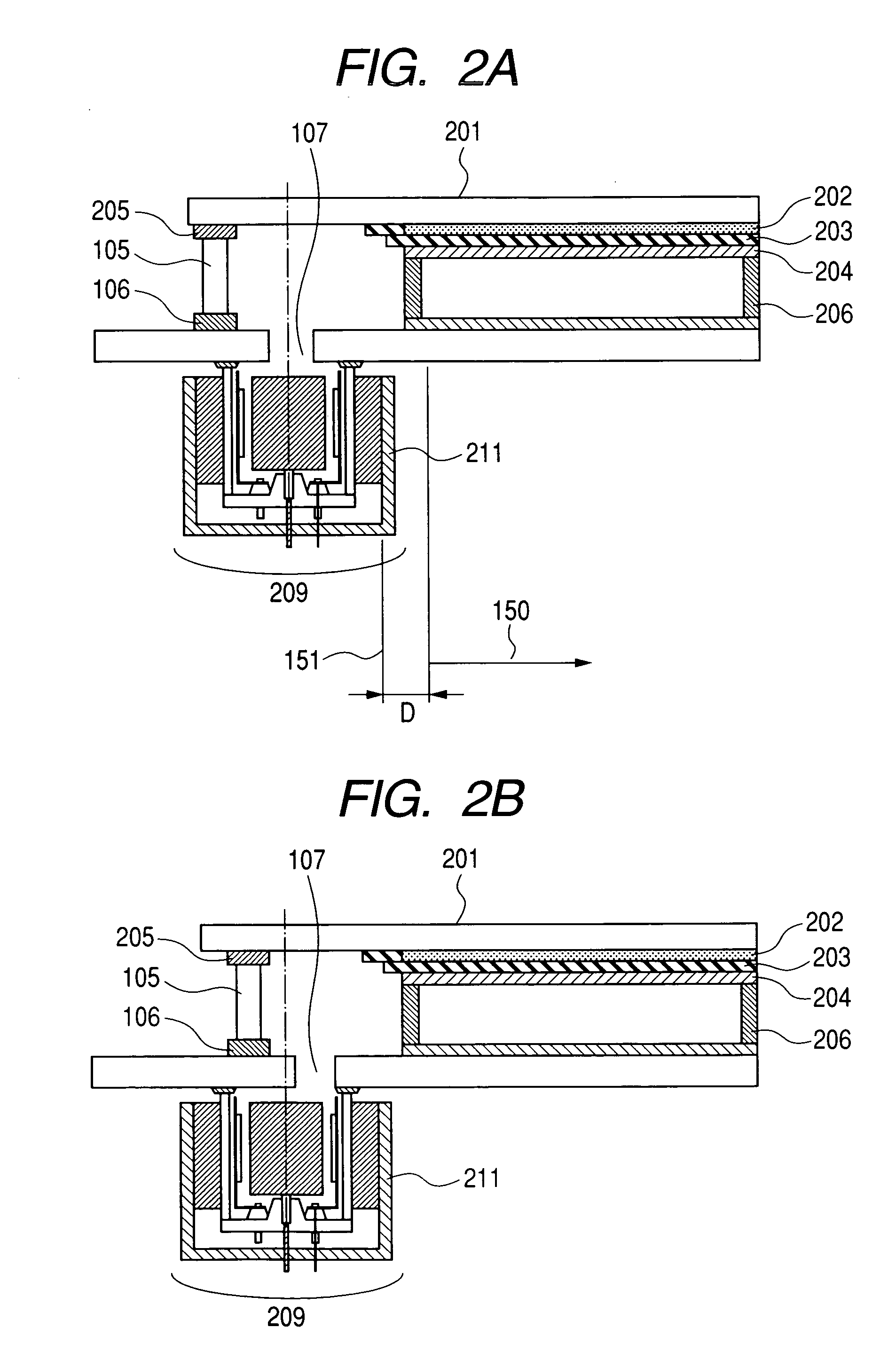
[0119] As is shown in FIG. 2A, an image display apparatus and an ion pump in the present embodiment were produced as in the case of Embodiment 1 except that an ion pump casing 112 was directly bonded to a rear plate 101 with frit glass 106.

[0120] A yoke 211 made of iron with a thickness of 2 mm was installed outside a magnet so that as many magnetic lines of force as possible could pass through the yoke. The magnet and the yoke were placed so as not to come right under an electron-emitting device 120 (an electron source). In the present embodiment, the magnet was arranged so that the end of the magnet could be separated from the nearest electron source by 10 mm. In order to separate the end of the magnet and the yoke from the electron source, a larger supporting frame 105 and a larger substrate for a face plate 201 than usual were used.

[0121] When a brightness distribution of the image display apparatus prepared in Embodiment 2 was measured, the brightness even around an ion pump ...

embodiment 3

[0124] As an ion pump is shown in FIG. 2B, the central axis of the ion pump was displaced from the central axis of an aperture portion 107 toward an opposite direction to an imaging region. By doing so, a supporting frame 105 and a substrate for a face plate 201 similar to Embodiment 1 could be used. Except the above points, an image display apparatus and the ion pump were produced as in the case of Embodiment 1. A yoke 211 made of iron with a thickness of 2 mm was installed outside a magnet so that as many magnetic lines of force as possible could pass through the yoke. The magnet and the yoke were placed so as not to come right under an electron-emitting device 120 (an electron source). In the present embodiment, the magnet was arranged so that the end of the magnet could be separated from the nearest electron source by 10 mm.

[0125] When a brightness distribution of the image display apparatus prepared in Embodiment 3 was measured, the brightness even around an ion pump was reduc...


PUM


Abstract

An image display apparatus for forming an image in an image displaying region provided with a vacuum chamber having an electron source substrate and an image forming substrate has an ion pump for evacuating the vacuum chamber by an action of a magnet-filed-forming portion through an aperture portion formed in the electron source substrate or an image displaying substrate, wherein the magnet-filed-forming portion is arranged so that a shadow formed by perpendicularly projecting the magnet-filed-forming portion onto the electron source substrate or the image forming substrate can be located outside the image displaying region.

Description

BACKGROUND OF THE INVENTION [0001] 1. Field of the Invention [0002] The present invention relates to an image display apparatus using an electron-emitting device. [0003] 2. Related Background Art [0004] A flat panel display which arranges many electron-emitting devices as electron sources on a planar substrate, irradiates an phosphor of an imaging member on a substrate with an electron beam emitted from an electron source on the opposite side to make the phosphor emit light and display images, needs to keep the inside of a vacuum chamber including the electron source and the imaging members into a high vacuum. This is because when a gas is generated in the vacuum chamber and the pressure increases, the gas adversely exerts an adverse effect on the electron sources to decrease an electron emission amount and hinder the display of a bright image, though the extent of the effect depends on the types of the gas. [0005] Gases generated from image display members accumulate in the vicinit...

Claims


Application Information

Patent Timeline
Patent Type & Authority Applications(United States)
IPC IPC(8): H01J1/62H01J63/04H01J29/94H01J31/12
CPCH01J7/14H01J7/18H01J31/127H01J29/94H01J9/385H01J1/30H01J9/38
Inventor TSUDA, HISANORIKAMIO, MASARUGOFUKU, IHACHIROSATO, YASUE
Owner CANON KK
Why Eureka
Try Eureka