Communication terminal and communication network

a terminal and communication network technology, applied in the field of communication networks, can solve the problems of packet signal interference or collusion, unstable single-path routing scheme, and conventional multi-path routing scheme, and achieve the effect of robust and stable communication routing

Inactive Publication Date: 2005-05-12
OKI ELECTRIC IND CO LTD
View PDF7 Cites 119 Cited by
  • Summary
  • Abstract
  • Description
  • Claims
  • Application Information

AI Technical Summary

Benefits of technology

[0013] By providing a substantially interference-free single-path route as well as a multipath backup route, the invention uses net...

Problems solved by technology

Single-path routing schemes are unstable because communication can be broken off if even a single terminal is disabled or moved to another location.
Conventional multipath routing schemes, however, invite a further problem.
As numerous paths crisscross the network between a source terminal and a destination terminal, neighboring terminals tend to start transmitting packets at identical times, causing the packet ...

Method used


Image

  • Communication terminal and communication network
  • Communication terminal and communication network
  • Communication terminal and communication network

Examples


first embodiment

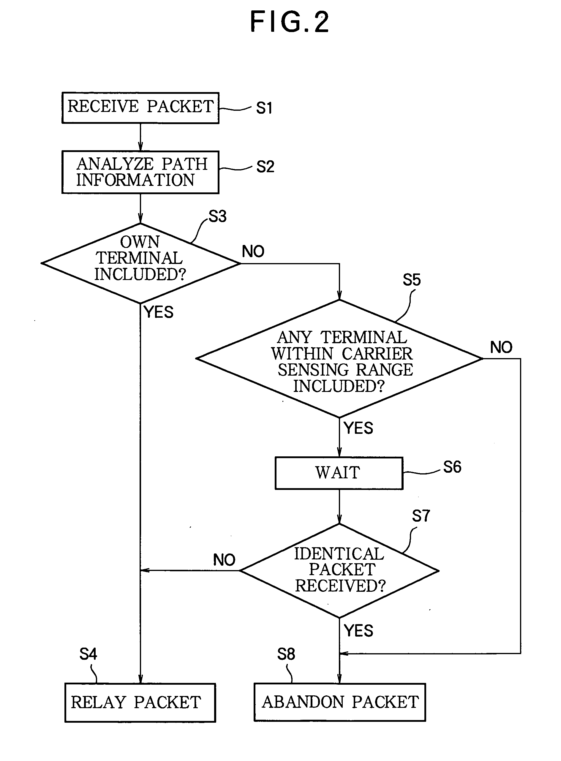
[0034] The first embodiment is based on a source routing scheme in which packets are transmitted with attached information specifying the entire single-path route. When a source terminal communicates with a destination terminal, the routing process includes the following five steps.

[0035] Step 1: To confirm the feasibility of communication with the destination terminal, the source terminal floods the network with packets requesting communication with the destination terminal. Each terminal, other than the destination terminal, that receives one of these packets adds its own terminal identifier (ID) and transmits the packet onward. The terminal ID is a communication interface address, an Internet protocol (IP) address, a media access control (MAC) address, or other identifying information stored in the terminal. When the destination terminal receives these packets, it analyzes the added IDs to find the shortest route from the source terminal.

[0036] Step 2: When the destination term...

second embodiment

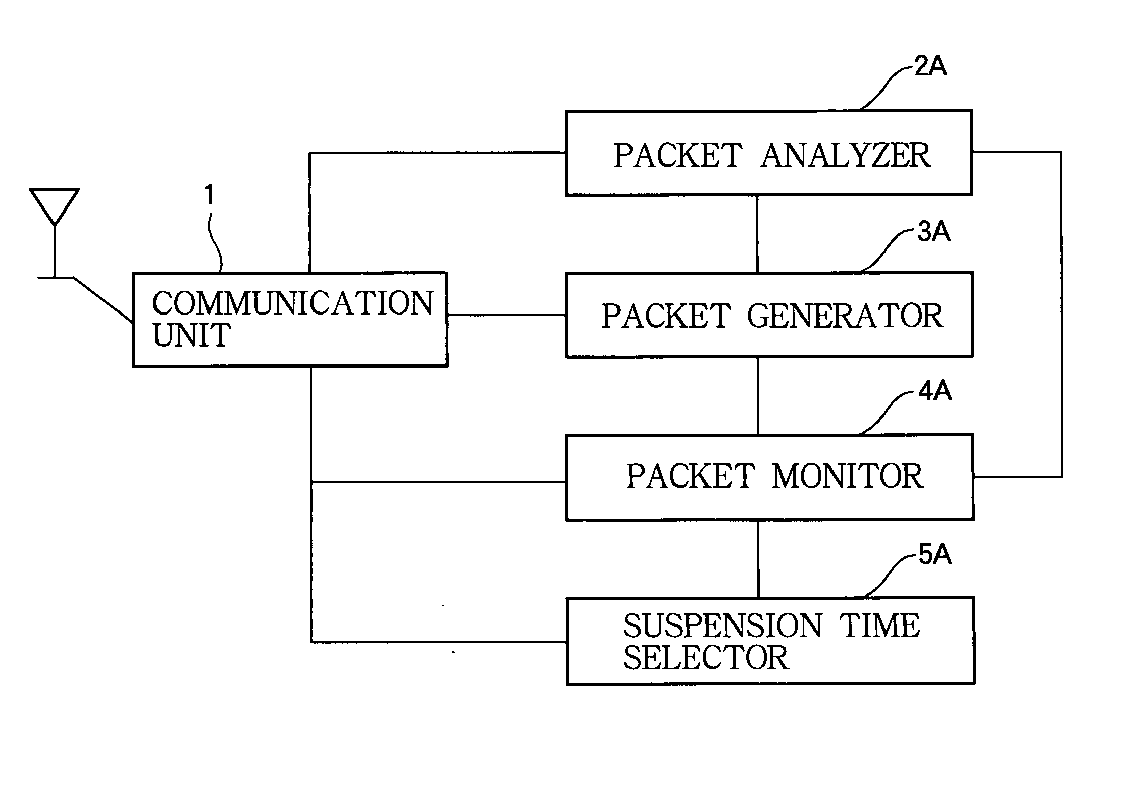
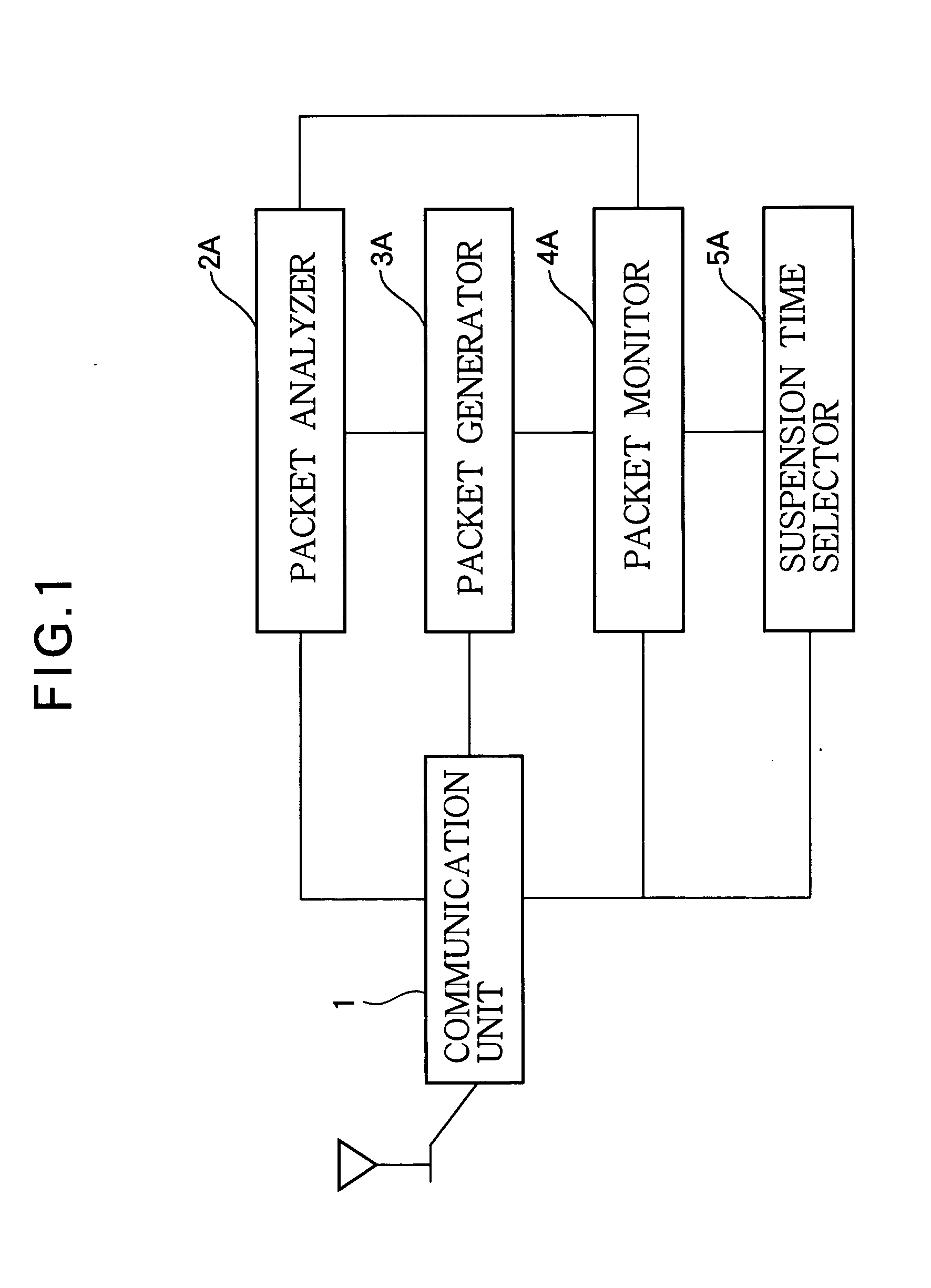
[0092] Referring to FIG. 25, a terminal in a second embodiment comprises a communication unit 1, a packet analyzer 2A, a packet generator 3A, a packet monitor 4A, and a suspension time selector 5B. The terminal structure is the same as in the first embodiment, except that a different suspension time selector 5B is employed. Only the function of the suspension time selector 5B will be described below.

[0093] Like the suspension time selector 5A in the first embodiment, the suspension time selector 5B sets the suspension time during which the packet monitor 4A retains a suspended packet. The suspension time selector 5B differs from the packet monitor 4B in that it is interconnected to the packet analyzer 2A, but not to the communication unit 1. The suspension time selector 5B uses the information provided by the packet analyzer 2A to monitor the transmission and reception of packets on the shortest path, and sets the suspension time for holding packets accordingly.

[0094] More specifi...

third embodiment

[0097] Referring to FIG. 26, a terminal in the third embodiment comprises a communication unit 1, a packet analyzer 2A, a packet generator 3A, a packet monitor 4A, and a suspension time selector 5C. The terminal structure is the same as in the first embodiment except for the use of a different suspension time selector 5C, so only the functions of the suspension time selector 5C will be described below.

[0098] Like the suspension time selector 5A in the first embodiment, the suspension time selector 5C sets the suspension time during which the packet monitor 4A holds a packet. The suspension time selector 5C differs from the suspension time selector 5A in that it is interconnected to the packet analyzer 2A as well as to the communication unit 1, and monitors both the carrier signal conditions and the packet transmission activity of nearby terminals in order to set the suspension time for holding packets.

[0099] The suspension time selector 5C sets the suspension time according to the...


PUM


Abstract

Each node or terminal in a communication network is capable of generating routing information for routing packets from an arbitrary source terminal to an arbitrary destination terminal on both a single-path route and a multipath route. The routing information is placed in packets transmitted to neighboring communication terminals, and analyzed in packets received from neighboring terminals. The single-path route is spatially or temporally separated from the multipath route so that the single-path route does not receive interference from the multipath route. Temporal separation may be effected by suspending the transmission of packets temporarily at each communication terminal on the multipath route. Spatial separation may be effected by using the routing information to designate different zones in the network, the single-path route being disposed in one zone, the multipath route in another zone.

Description

BACKGROUND OF THE INVENTION [0001] 1. Field of the Invention [0002] The present invention relates to a communication network such as an ad hoc network comprising a plurality of communication terminals, to the terminals in the network, and in particular to the routing method employed in the network. [0003] 2. Description of the Related Art [0004] Communication in an ad hoc network takes place by the routing of packets from a source node or terminal to a destination node or terminal on a path that may lead through one or more intermediate or relay nodes or terminals. (‘Terminal’ will be used below as a synonym for ‘node’.) All of the terminals in the network are capable of operating as routers, that is, of designating the paths or routes that packets will follow. The routing methods employed in an ad hoc network include single-path schemes such as the one described in, for example, ‘Ad hoc On-Demand Distance Vector (AODV) Routing’, available on the Internet as of Oct. 16, 2003 at URL ...

Claims


Application Information

Patent Timeline
IPC IPC(8): H04L12/56H04W40/00H04W84/18
CPCH04L45/20H04W84/18H04W40/00H04L45/24
Inventor NAKAMURA, NOBUYUKIKADO, YOUITI
Owner OKI ELECTRIC IND CO LTD
Why Eureka
Try Eureka