
Cartridge-type lithium ion polymer battery pack

Active Publication Date: 2005-05-12
LG ENERGY SOLUTION LTD
View PDF6 Cites 91 Cited by
  • Summary
  • Abstract
  • Description
  • Claims
  • Application Information

AI Technical Summary

Benefits of technology

[0010] It is still another object of the present invention to provide a cartridge-type lithium ion polymer battery pack which can be used as a power source for an instrument requiring high output such as a motor-drivable car, in the form of multiple layers of battery packs that cause heat generated from the battery packs to be discharged to the exterior efficiently.

Problems solved by technology

However, such a conventional battery module has a problem in that batteries forming a battery assembly have a cylindrical shape and relatively large length and thus the whole volume of the battery module undesirably becomes large.
Further, because the battery assembly is large, it is not handy to laminate and integrally fix a plurality of battery assemblies in order to manufacture a battery module conformed to the electric power requirement for a desired instrument.
In another aspect, such a conventional battery module has a complicated structure because electrodes of each battery in a battery assembly are connected via connectors on the battery retaining boards.
Moreover, connecting electrodes of each battery via connectors on the battery retaining boards is very cumbersome work.
Additionally, when multiple battery modules are laminated so as to be applied as a power source for an instrument requiring high output (for example a motor-drivable car), there is a great possibility of batteries being overheated while the battery modules are operated for a long time, because batteries in a battery assembly forming a battery module are in close contact with each other and surrounded with a shell.

Method used


Image

  • Cartridge-type lithium ion polymer battery pack
  • Cartridge-type lithium ion polymer battery pack
  • Cartridge-type lithium ion polymer battery pack

Examples


Embodiment Construction

[0021] Reference will now be made in detail to the preferred embodiments of the present invention as shown in FIGS. 2 to 7.

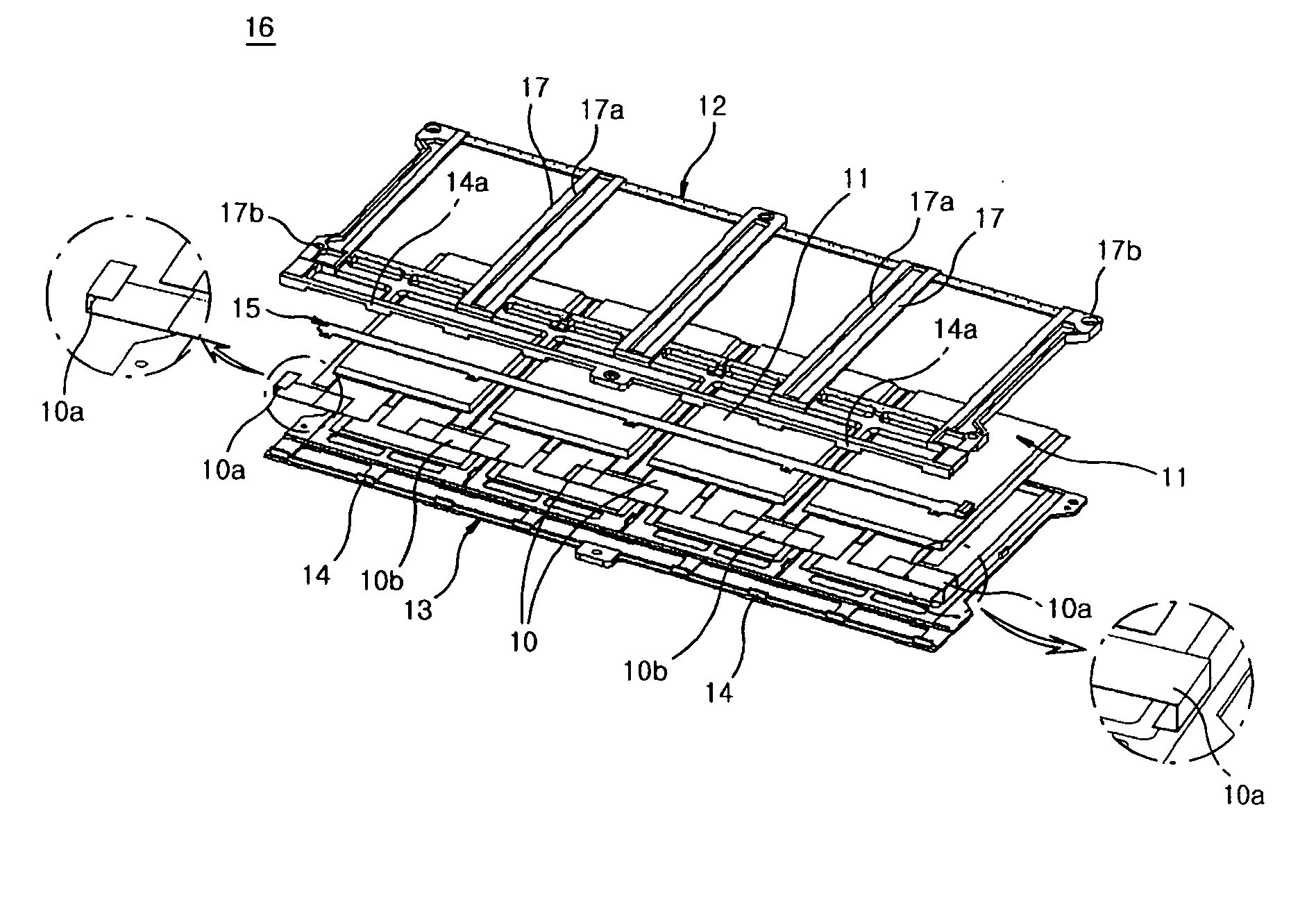
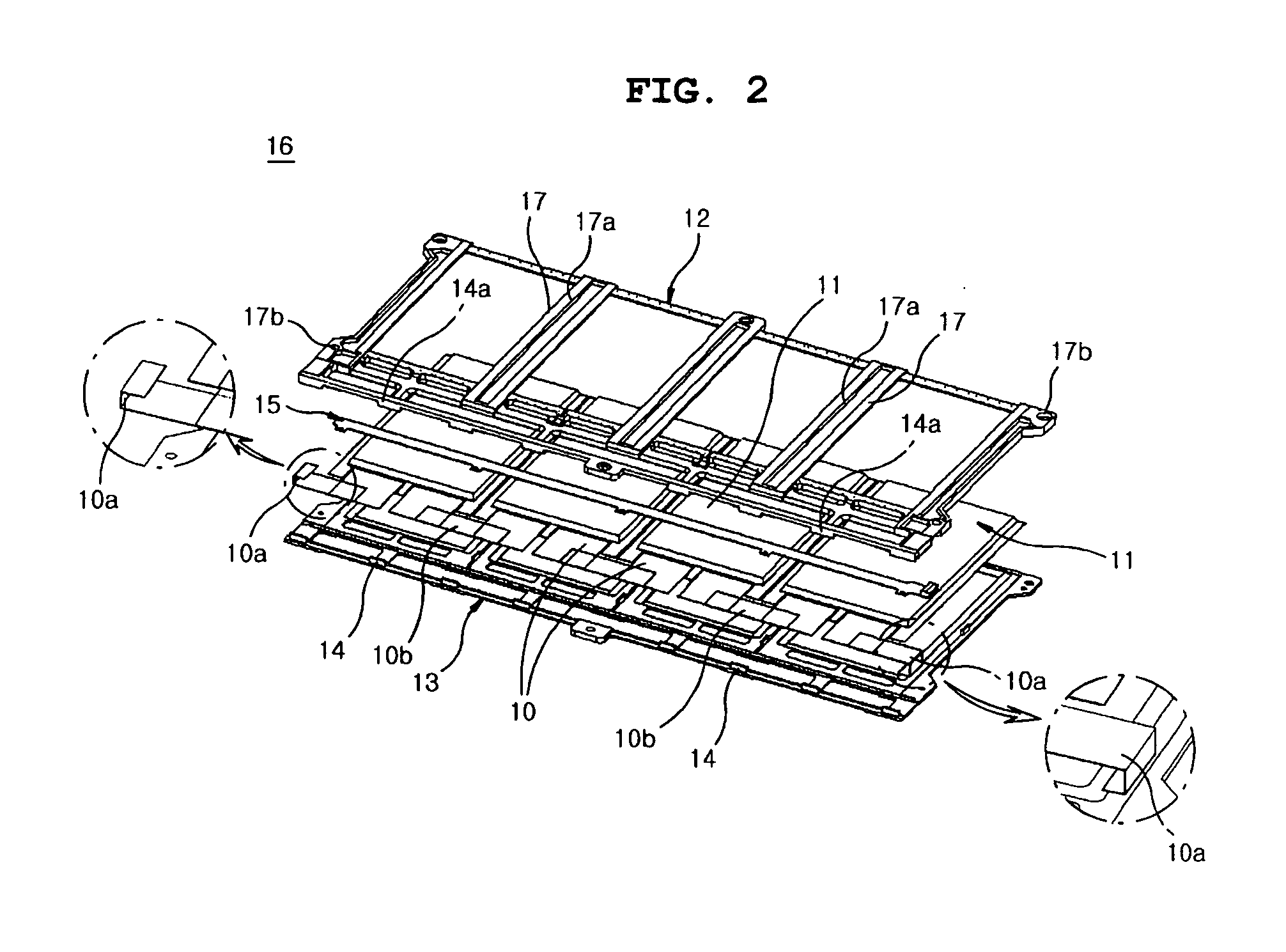
[0022]FIG. 2 is a schematic exploded perspective view showing a cartridge-type lithium ion polymer battery pack according to a preferred embodiment of the present invention. FIG. 3 is a schematic perspective view showing a cartridge-type lithium ion polymer battery pack according to a preferred embodiment of the present invention.

[0023] As shown in FIGS. 2 to 7, the battery pack according to the present invention includes: at least two lithium ion polymer batteries 11 in which adjacent electrode tabs 10 (or electrode terminals) are connected to each other so as to form a predetermined series circuit with a desired instrument (not shown); and an upper plate 12 and a lower plate 13 disposed at the top and the bottom of the whole lithium ion polymer batteries, respectively, and coupled to each other so that each lithium ion polymer battery 11 is partially covered...


PUM


Abstract

Disclosed is a cartridge-type lithium ion polymer battery pack including: at least two lithium ion polymer batteries in which adjacent electrode tabs are connected to each other so as to form a predetermined series circuit with a desired instrument; and an upper plate and a lower plate disposed at the top and the bottom of the whole lithium ion polymer batteries, respectively, and coupled to each other so that each lithium ion polymer battery is partially covered with them. Multiple layers of the battery packs are laminated and fixed with ease so as to conform to the electric power requirement for a desired instrument.

Description

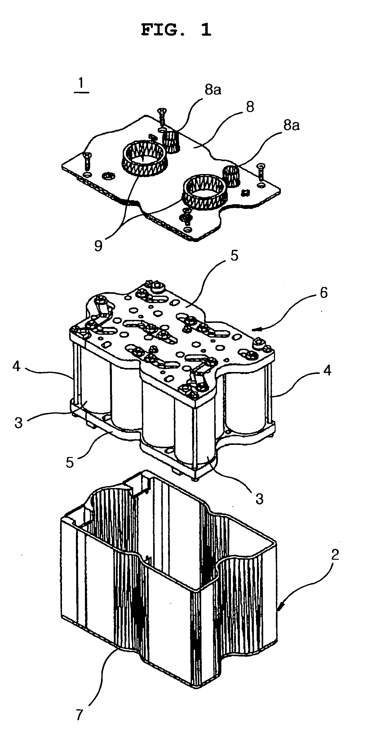
TECHNICAL FIELD [0001] The present invention relates to a lithium ion polymer battery pack. More particularly, the present invention relates to a cartridge-type lithium ion polymer battery pack, wherein at least two pouch-shaped lithium ion polymer batteries are fixed with an upper plate and a lower plate so as to be partially covered with the plates, thereby providing a cartridge-type battery pack, and multiple layers of such cartridge-type battery packs are laminated and connected to each other in series so as to conform to the electric power requirement for a desired instrument and then are fixed detachably by means of bolts and nuts, or elastic fasteners. BACKGROUND ART [0002] In general, as shown in FIG. 1, a battery module 1 includes: a shell 2 having a predetermined housing space that is open at the top and the bottom thereof; a battery assembly 6 having a plurality of cylindrical batteries 3 disposed in such a manner that axis lines of the batteries are parallel to each othe...

Claims


Application Information

Patent Timeline
IPC IPC(8): H01M6/40H01M6/46H01M6/50H01M10/48H01M10/60H01M50/211H01M50/503H01M50/51
CPCH01M2/1061H01M2/202H01M6/40H01M6/46Y02T10/7011H01M10/0525H01M10/0565H01M10/486Y02E60/122H01M6/5044Y02E60/10Y02P70/50H01M50/51H01M50/503H01M50/211H01M50/20Y02T10/70
Inventor RO, JONG YULNAMGOONG, JOHN E.
Owner LG ENERGY SOLUTION LTD
Learn More