Golf club head

a golf club and club head technology, applied in the field of golf club heads, can solve the problems of not being sufficiently attempted in conventional heads, unreasonable to expect a golfer of average skill, etc., and achieve the effect of increasing the region and high the coefficient of restitution

Active Publication Date: 2005-05-12
SUMITOMO RUBBER IND LTD
View PDF5 Cites 72 Cited by
  • Summary
  • Abstract
  • Description
  • Claims
  • Application Information

AI Technical Summary

Benefits of technology

[0006] It is therefore, an object of the invention is to provide a golf club head, which has a increased region having a high coefficient of restitution.

Problems solved by technology

On the other hand, it is unreasonable to expect a golfer of average skill to always hit a ball at the same point on the face surface.
However, this hasn't been sufficiently attempted yet in conventional heads.

Method used


Image

  • Golf club head
  • Golf club head
  • Golf club head

Examples


examples

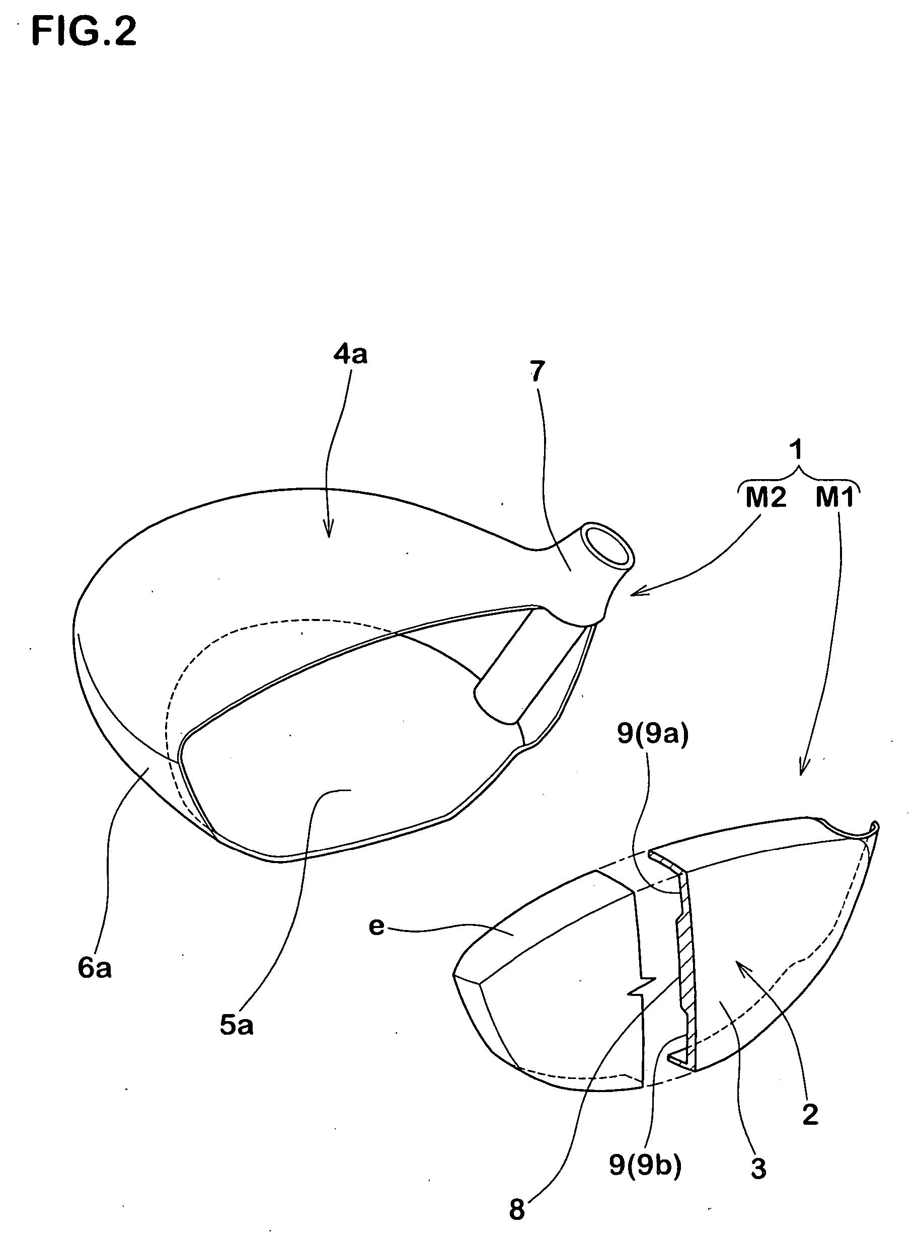
[0066] The head of a driver having a head volume of 360 cm3 and a real loft angle of 10 degrees was prototyped on the basis of the specifications of Table 1. Each head was manufactured by welding a face member made of a forged product in bowl form to a head body made of a casted product, both of which are shown in FIG. 2. Here, Ti-15V-6Cr-4Al (DAT55G) was utilized as the material for the face member, and Ti-6Al-4V was utilized as the material for the head body, respectively. Then, a shaft was attached to each prototype head so as to manufacture a wood type golf club having a full length of 45 inches. In addition, for the purpose of comparison, golf clubs (Comparative Examples 1 and 2) where the peripheral thin portion 1 is formed to have a thickness of one type and a golf club (Comparative Example 3) having no portion of a varying thickness were also manufactured. The gist of the tests is as follows.

[0067] The coefficients of restitution of the heads were measured on the basis of ”...


PUM


Abstract

A golf club head having a face portion that hits a ball, which includes: a center thick portion; a portion of a varying thickness in annular form; and a peripheral thin portion provided around the portion of a varying thickness, where the peripheral thin portion of which the thickness is the smaller than that of the center thick portion. The peripheral thin portion includes a first thin portion and a second thin portion. The first thin portion is provided in at least one portion of a sole portion, a toe portion and a heel portion of the peripheral thin portion.

Description

BACKGROUND OF THE INVENTION [0001] 1. Field of the Invention [0002] The present invention relates to a golf club head that is helpful for increasing a region of a high coefficient of restitution so as to increase carry for a golfer of average skill. [0003] 2. Description of the Background Art [0004] Importance is placed on the function of increasing the carry of a hit ball of a golf club head, in particular, a wood type golf club head. Therefore, a variety of methods for increasing the coefficient of restitution of the head has been proposed by respective golf club manufacturers. According to one of such methods for increasing the coefficient of restitution of the head, a structure is known where a thin portion in annular form is provided on the back side of the face portion so that the face bends sufficiently at the time when a ball is hit as described in the Published patent application No.H09-192273, or No.H09-299519. In addition, it is known that a thin portion where the thickne...

Claims


Application Information

Patent Timeline
Patent Type & Authority Applications(United States)
IPC IPC(8): A63B53/04A63B102/32
CPCA63B53/0466A63B2053/0408A63B2053/0462A63B2053/0458A63B2053/0416A63B60/00A63B53/0408A63B53/0416A63B53/0458A63B53/0462
Inventor HIRANO, TOMOYA
Owner SUMITOMO RUBBER IND LTD
Why Eureka
Try Eureka