Training machine

a training machine and weight technology, applied in the field of training machines, can solve the problems of providing the exerciser with a load which becomes greater, suffering from mental stress, and troublesome for a beginner to exercise with control of the movement, and achieve the effect of adjusting the overall weight of the weight assembly with eas

Active Publication Date: 2005-05-12
TANREN
View PDF5 Cites 14 Cited by
  • Summary
  • Abstract
  • Description
  • Claims
  • Application Information

AI Technical Summary

Benefits of technology

[0029] In the training machine defined in claim 11, the joining member provided together with the weight connecting rod and the weights for constituting the weight assembly is inserted across the recess in the desired weight into the connecting hole in the weight connecting rod. With the joining member extending across the recess in the desired weight and the through hole in the weight connecting rod, the desired weight is joined to the weight connecting rod. When the weight connecting rod is moved upward by the movement of the movable member connected by the connecting means, the joining member lifts up the desired weight. As a result, the desired weight and the other weights located above the desired weight can all be lifted up. By selecting one of the weights in to which the joining member is inserted, a desired number of the weights to be joined to the weight connecting rod can be determined thus adjusting the overall weight of the weight assembly with ease.

Problems solved by technology

However, the training machine has two major drawbacks, which are based on the use of weights.
Secondly, when the weights are lifted up, they resist against their gravity and thus provide the exerciser with a load which becomes greater when the speed of the training movement is increased.
As a result, the exerciser has to concentrate its attention on the speed and will thus suffer from a mental stress.
It is particularly troublesome for a beginner to exercise with control of the movement.

Method used


Image

  • Training machine
  • Training machine
  • Training machine

Examples


first embodiment

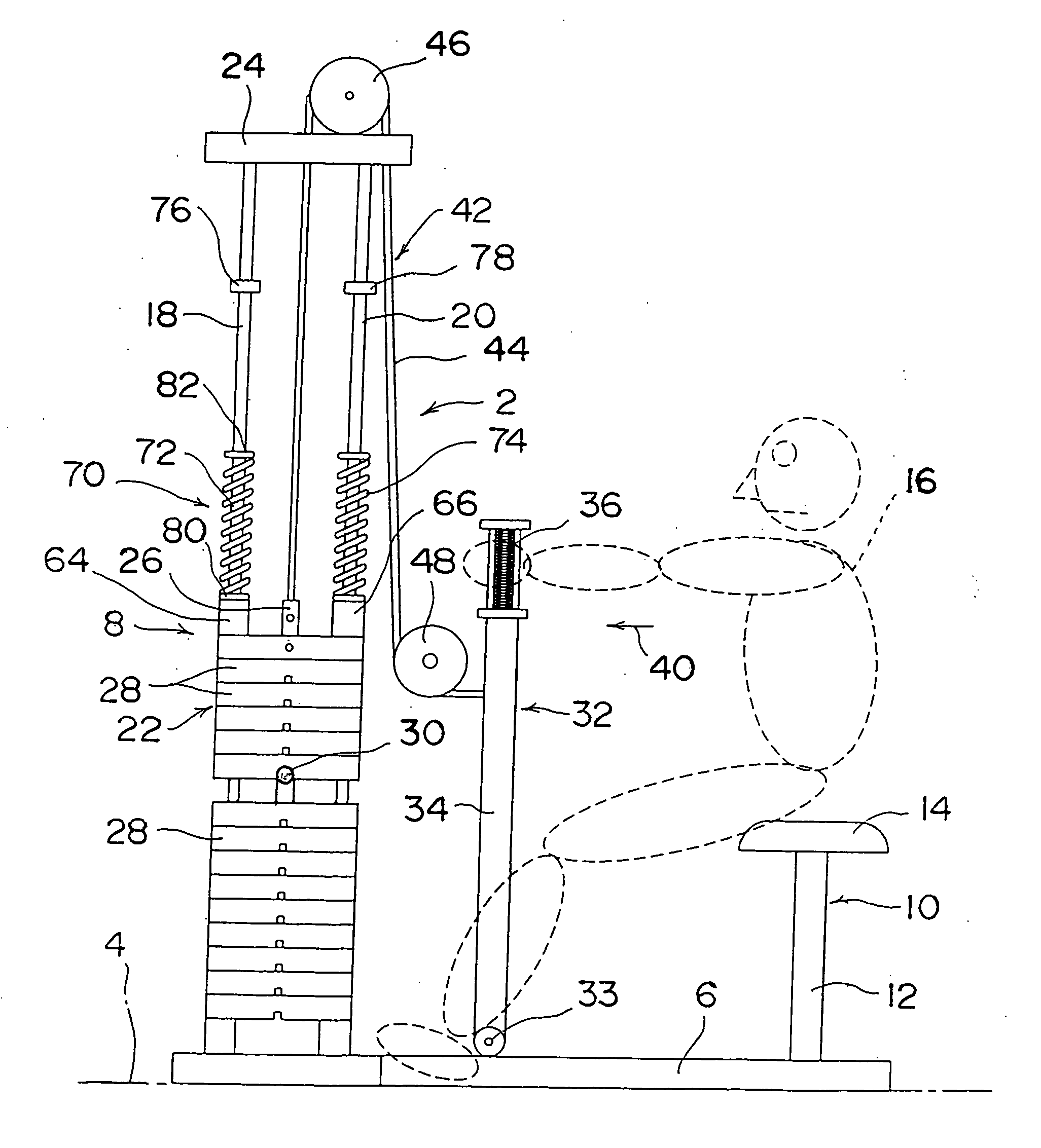
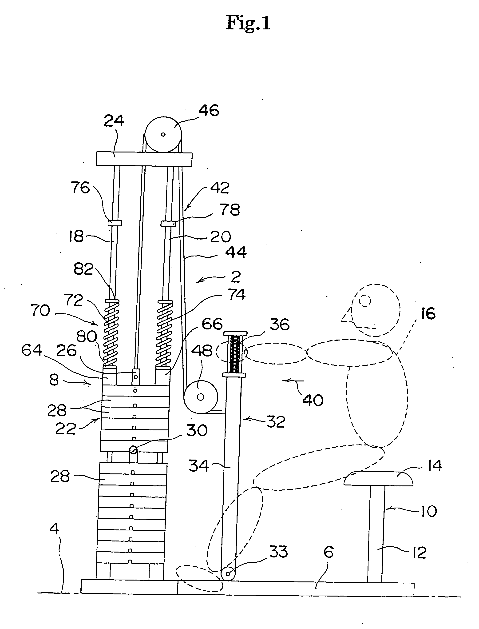
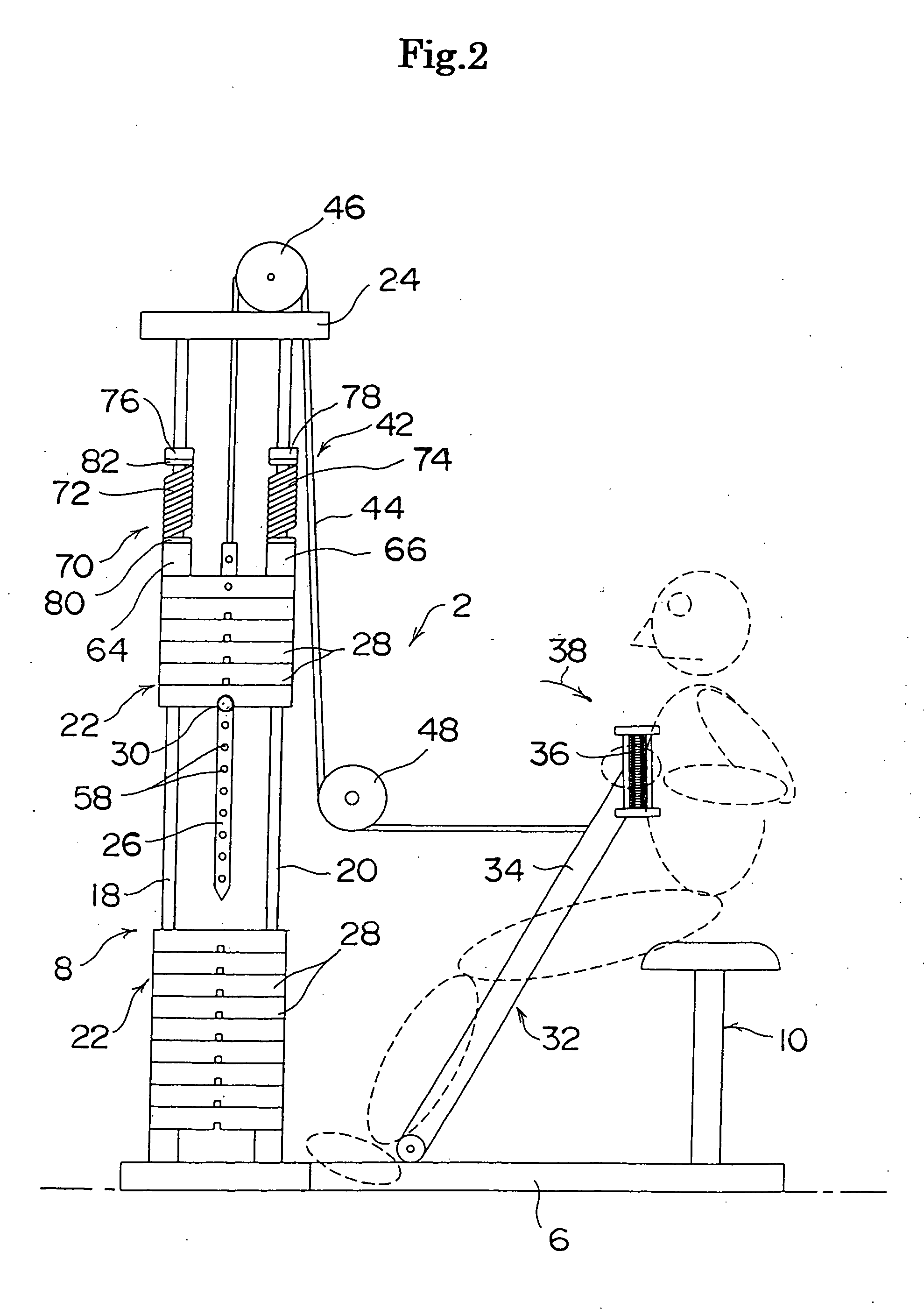
[0047] A training machine according to the first embodiment of the present invention will be described referring to FIGS. 1 to 5.

[0048] As shown in FIGS. 1 and 2, the training machine 2 of the first embodiment has a base 6 arranged for installation, for example, on the floor 4 of a training gymnasium. In this embodiment, the base 6 is accompanied at one side (on the left shown in FIG. 1 or 2) with a load exerting means 8 and at the other side (on the right shown in FIG. 1 or 2) with a stool 10. The stool 10 comprises a leg 12 fixedly mounted to the base 6 and a seat 14 mounted on the top of the leg 12. During the training action, an exerciser 16 sits on the seat 14 of the stool 10.

[0049] The load exerting means 8 comprises a pair of guide posts 18 and 20 arranged to extend vertically and upwardly from the base 6 and a weight assembly 22 provided for upward and downward movement along the guide posts 18 and 20. The two guide posts 18 and 20 are joined at the uppermost end to each o...

second embodiment

[0070] A training machine according to the second embodiment of the present invention will be described referring to FIGS. 6 and 7. FIG. 6 is a side view schematically showing the training machine of the second embodiment. FIG. 7 is a side view of the training machine shown in FIG. 6 with its weight assembly lifted up to the upper most point. Like components are denoted by like numerals as those of the first embodiment and will be explained in no more detail.

[0071] As shown in FIGS. 6 and 7, the training machine 2A is designed for development of the abdominal muscles of an exerciser 16. The training machine 2A has a stool 10A mounted on substantially a lengthwise center of a base 6A thereof. A load exerting means 8 which is identical to that of the first embodiment is provided at one side of the base 6A (on the left in FIGS. 6 and 7) while a foot rest 92 is provided at the other side (on the right in FIGS. 6 and 7).

[0072] The movable member 32 is modified to a movable member 32A w...

third embodiment

[0075] A training machine according to the third embodiment of the present invention will be described referring to FIGS. 8 and 9. FIG. 8 is a side view schematically showing the training machine of the third embodiment. FIG. 9 is a side view of the training machine shown in FIG. 8 with its weight assembly lifted up to the uppermost point. The third embodiment like the first embodiment is designed for development of the muscles of the arms of an exerciser, where the counter-force exerting means and its relevant arrangement are modified.

[0076] As shown in FIGS. 8 and 9, the training machine 2B is arranged in which the movable member 32 has a pivotable bar 34 pivotably mounted at the lowermost end by a pivot 33 to abase 6. Also, an expandable member 112 is provided between the pivotable bar 34 and the base 6. The expandable member 112 comprises, for example, a main body 114 as a cylinder housing and an expandable rod 116 as a cylinder rod. The expandable rod 116 is inserted into the ...


PUM


Abstract

A training machine is provided comprising a base (6) arranged for placement on the floor (4), a movable member (32) provided on the base (6) to be moved by the training action, and a load exerting means (8) for exerting a load to control the movement of the movable member (32). The load exerting means (8) has a weight assembly (22) thereof arranged to be lifted vertically by the movement of the movable member (32) as resisting the gravity and particular is accompanied with a counter-force exerting means (70) arranged at the weight assembly (22) and/or the movable member (32) for exerting a returning force on the movable member (32) at the timing of shift from the upward movement to the downward movement of the weight assembly (22). The counter-force exerting means (70) comprises, for example, coil springs (72, 74) and movement stoppers (76, 78) for restricting the movement of the coil springs (72, 74).

Description

FIELD OF THE INVENTION [0001] The present invention relates to a training machine for lifting weights as resisting against the gravity in order to exhaust and thus develop the muscles. BACKGROUND OF THE INVENTION [0002] Training machines have been provided in the market for lifting weights vertically as resisting against the gravity to develop the muscles. Such a training machine basically comprises a base placed on the floor, a movable member arranged movable in response to the movement of the body of an exerciser, and a load exerting means for exerting a load to control the movement of the movable member. The load exerting means includes weights provided for movement vertically along guide posts and connecting wires connecting between the weights and the movable member. (See Japanese Patent Laid-open Publication (Heisei) 6-7475). [0003] In action of the training machine, the movable member is moved to a target position by an exerciser contracting its muscles for physical training....

Claims


Application Information

Patent Timeline
Patent Type & Authority Applications(United States)
IPC IPC(8): A63B21/00A63B21/02A63B21/05A63B21/06A63B21/062A63B21/08A63B69/06
CPCA63B21/023A63B21/05A63B21/0615A63B21/062A63B21/08A63B21/1469A63B2022/0084A63B21/1492A63B21/154A63B21/159A63B23/03525A63B2021/0614A63B2021/0623A63B21/1488A63B21/0626A63B21/0628A63B21/063A63B21/4035A63B21/4045A63B21/4047A63B21/06A63B21/075
Inventor OOKA, AKIHIRO
Owner TANREN
Why Eureka
Try Eureka