Fluid suspended self-rotating body and method

a self-rotating body and floating technology, applied in the field of self-starting and self-powered display devices, can solve the problems of consuming a great deal of electrical power, complex and bulky counter-torque-producing mechanisms, and most prior embodiments that are not totally free of external connection

Inactive Publication Date: 2005-05-19
TURTLETECH DESIGN
View PDF13 Cites 26 Cited by
  • Summary
  • Abstract
  • Description
  • Claims
  • Application Information

AI Technical Summary

Benefits of technology

[0006] The principal and secondary objects of this invention are to provide the simplest and least power-demanding rotating display that can operate for extremely long periods of time without any apparent driving mechanism, input of power, or support bearing, and that may be suitable for use as a toy, advertising medium, novelty, or robotic component of a remote space or underwater installation.

Problems solved by technology

Most prior embodiments are not totally free of external connection.
If they are not firmly anchored to an outer support, they require complex and bulky countertorque-producing mechanisms such as fan blades or other internal heavy and complex systems that consume a great deal of electrical power.
This patent does not address the avoidance of bubbles resulting from the expansion of the container and problems created by excessive internal pressure resulting from absorption of ambient moisture.

Method used


Image

  • Fluid suspended self-rotating body and method
  • Fluid suspended self-rotating body and method
  • Fluid suspended self-rotating body and method

Examples


third embodiment

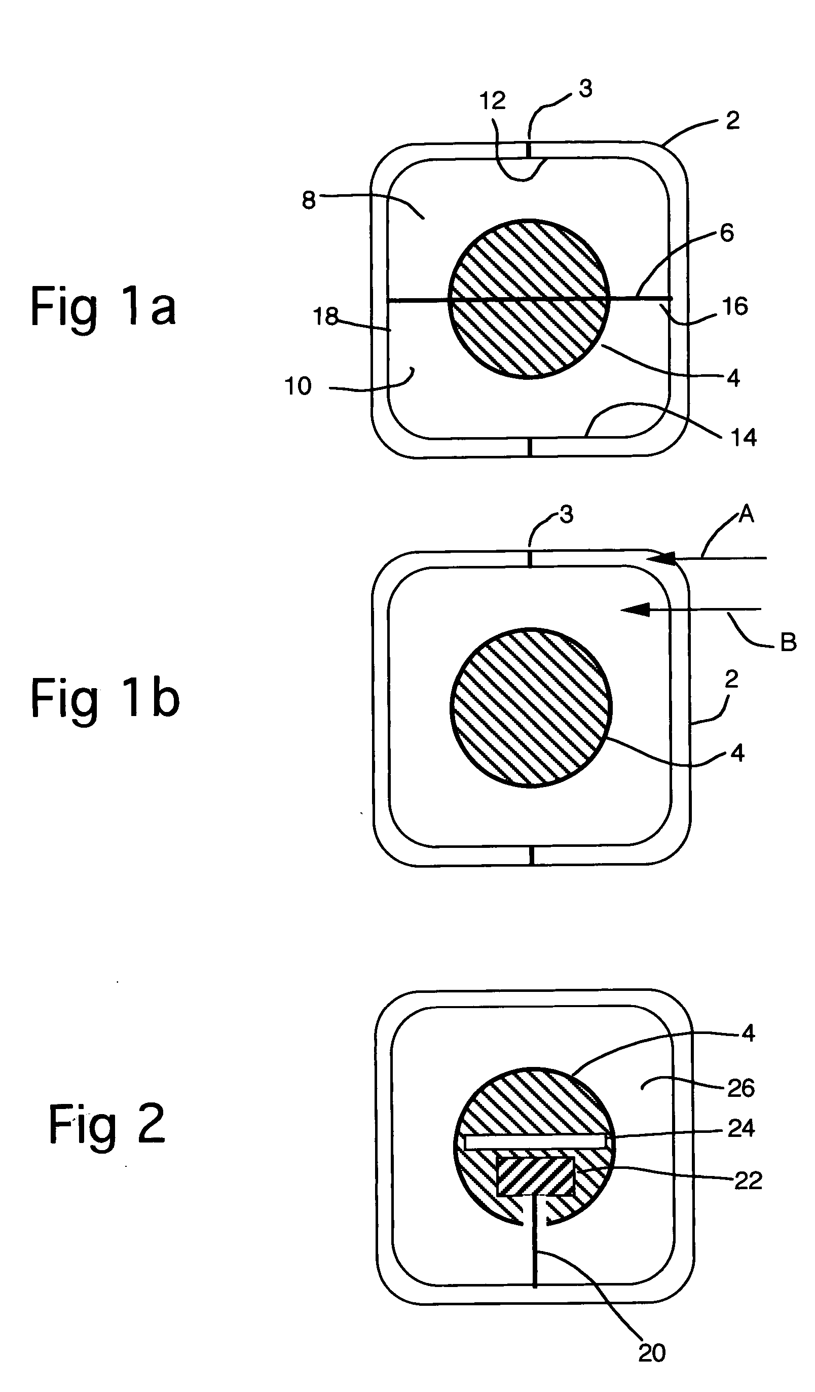
[0061] The structure and operation of a third embodiment, shown in FIG. 5, are similar to the embodiment of FIG. 3, except the ball 30 and the fluid 26 are similar to their counterparts shown in FIG. 2. Thus, a motor assembly 28 drives the rotation of the ball 3, that is immersed in a fluid 26 and supported by a pillar 20, the rotor of the motor being secured to the pillar.

fourth embodiment

[0062]FIGS. 6a and 6b show a fourth embodiment, which includes a satellite assembly 46, comprising a satellite ball 48 embedded within a satellite shell 50. A ball assembly 52 comprises a ball 4 embedded within a ball shell 54. The satellite assembly 46 and the ball assembly are both supported by the buoyant forces of a lighter fluid 8 and a heavier fluid 10, to float near the fluid interface 6. The satellite shell 50 and the ball shell 54 are preferably both made of a material having an index of refraction substantially similar to those of the fluids and enclosure that will be essentially not visible to an observer, by virtue of the same optical principles described for the embodiment of FIG. 1.

[0063]FIG. 6b shows the ball assembly 52 and the satellite assembly essentially in contact and floating roughly in the center of the case 2 as would occur due to surface tension with the proper choice of fluids and materials. For example, the satellite shell 50 and the ball shell 52 can be m...


PUM


Abstract

In a display device where a moving object is immersed in a fluid filling a transparent sealed, vesel (72) and is rotated by an internal electrical mechanism that derives it power from a photo cell (128) and its counter torque from an internal compass (140), the index of refraction of the fluid is adjusted by addition of water to match the index of refraction of the vesel material. The formula of the fluid is also tailored to minimize, absorption of ambient moisture into the vessel. In one embodiment of the electrical spinning mechanism, the magnet acts both as a biasing compass and as a magnetic field generator for the motor. In a second embodiment of the spinning mechanism, the stator is constituted by a multipole ring-shaped magnet (120) that does not interfere with the operation of the biasing compass magnet (140). Multiple windings in the electrical spinning mechanism are energized through a split-ring and brush commutator (92) that use the mechanism shaft (122) as conductor.

Description

FIELD OF THE INVENTION [0001] The instant invention relates to self-starting and self-powered display devices, and more particularly, to self-spinning globes powered by radiated energy. BACKGROUND OF THE INVENTION [0002] Various types of novelty structures which move with either no apparent support, drive mechanism, or power input are often used as toys, decorative conversation pieces or advertising media. Various embodiments of such structures have been disclosed in U.S. Pat. No. 5,435,086 Huang et al., Japanese Patents Nos. 10137451, 101431101, and 10171383, all by Hirose Mamoru, Japanese Patents Nos. 7210081, 7219426, and 7239652 all to Taragi Hiroshi and German Patents Nos. DE19706736 Fushoellier, DE3725723 Steinbrinck, and DE 41377175 Lang. Most prior embodiments are not totally free of external connection. If they are not firmly anchored to an outer support, they require complex and bulky countertorque-producing mechanisms such as fan blades or other internal heavy and complex...

Claims


Application Information

Patent Timeline
Patent Type & Authority Applications(United States)
IPC IPC(8): A63H23/08A63H33/00G09F19/02
CPCG09F19/02
Inventor FRENCH, WILLIAM W.
Owner TURTLETECH DESIGN
Why Eureka
Try Eureka