Fuel injection system for an internal combustion engine

a fuel injection system and internal combustion engine technology, applied in the direction of machines/engines, electric control, speed sensing governors, etc., can solve the problems of overshoot of fuel pressure, abnormal high-pressure condition of high-pressure fuel portions, and excessive feedback correction quantity for replenishing pump pressure-supply quantity, so as to prevent deterioration of controllability for pressure

Active Publication Date: 2005-05-19
DENSO CORP
View PDF7 Cites 82 Cited by
  • Summary
  • Abstract
  • Description
  • Claims
  • Application Information

AI Technical Summary

Benefits of technology

[0009] It is an object of the present invention to provide a fuel injection system for an internal combustion engine which can prevent the occurrence of a rise in fuel pressure greater than necessary caused by an excessive learning of the integral compensation quantity upon detection of a pressure-supply defect of a fuel supply pump and can thereby prevent deterioration of controllability for the pressure of fuel supplied from the fuel supply pump to a fuel injection valve. It is another object of the present invention to provide a fuel injection system for an internal combustion engine which can prevent the occurrence of an erroneous learning of a mechanical individual difference or a physical change of a fuel supply pump upon detection of a pressure-supply defect of the fuel supply pump and can thereby prevent deterioration of the controllability for the pressure of the fuel supplied from the fuel supply pump to a fuel injection valve.
[0010] Therefore, according to one aspect of the present invention, updating of an integral compensation quantity is stopped and a last-time integral term is held and continued when a pressure-supply defect of a fuel supply pump is detected. With this arrangement, a greater rise than necessary of the pressure of fuel supplied under pressure from the fuel supply pump to a fuel injection valve, which is caused by an excessive learning of the integral compensation quantity in the event of occurrence of a pressure-supply defect of the fuel supply pump, e.g., the occurrence of overshoot of the fuel pressure in which an actual fuel pressure in a common rail or in a fuel pipe becomes higher than a target fuel pressure, can be prevented. Consequently, it becomes possible to prevent deterioration of the controllability for the pressure of fuel supplied under pressure from the fuel supply pump to the fuel injection valve. Moreover, since it is possible to prevent deterioration of a pressure-resistant structure of a fuel pipe line in the fuel injection system for an internal combustion engine, it is possible to prevent leakage of the fuel from the fuel supply pump or the fuel injection valve to the exterior and hence possible to improve the reliability of each product.

Problems solved by technology

However, in the conventional accumulator-type fuel injection system, the feedback correction quantity tends to become too large for replenishing the pump pressure-supply quantity which becomes short in the normal control (normal) mode corresponding to the normal function of the fuel supply pump.
As a result, when the actual fuel pressure rises to a higher extent than necessary in comparison with the target fuel pressure, an overshoot of the fuel pressure occurs.
This means that the fuel pressure exceeds an upper-limit value, which the accumulator-type fuel injection system permits and an abnormal high-pressure condition of the high-pressure fuel portion in the accumulator-type fuel injection system is continued until a re-learning of the integral compensation quantity is established.
As a result, deterioration of a pressure-resistant structure of the fuel pipeline is accelerated.
This causes a factor of deterioration in the reliability of products such as leakage of the fuel from the fuel supply pump or from the fuel injection valve to the exterior.
Moreover, the overshoot of the fuel pressure caused by an excessive integral compensation quantity may exceed a valve opening pressure of a pressure limiter installed in the common rail and open the valve of the pressure limiter for avoiding the abnormal high-pressure condition of the high-pressure fuel portion in the accumulator type fuel injection system.
With the pressure limiter opened, a lowering of the common rail pressure obstructs a satisfactory fuel injection and causes a lowering in output of the internal combustion engine or deterioration (lowering) of the valve opening pressure in the pressure limiter.
Therefore, when the learning of the pump machine difference is continued in the event of occurrence of a pressure-supply defect failure of the fuel supply pump, an erroneous learning value (or learning quantity) is acquired and it is likely that the subsequent controllability for the fuel pressure in the common rail may be rather deteriorated.

Method used


Image

  • Fuel injection system for an internal combustion engine
  • Fuel injection system for an internal combustion engine
  • Fuel injection system for an internal combustion engine

Examples


first embodiment

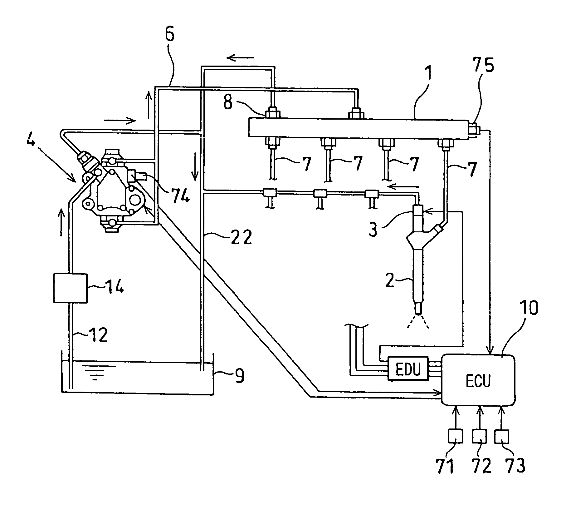
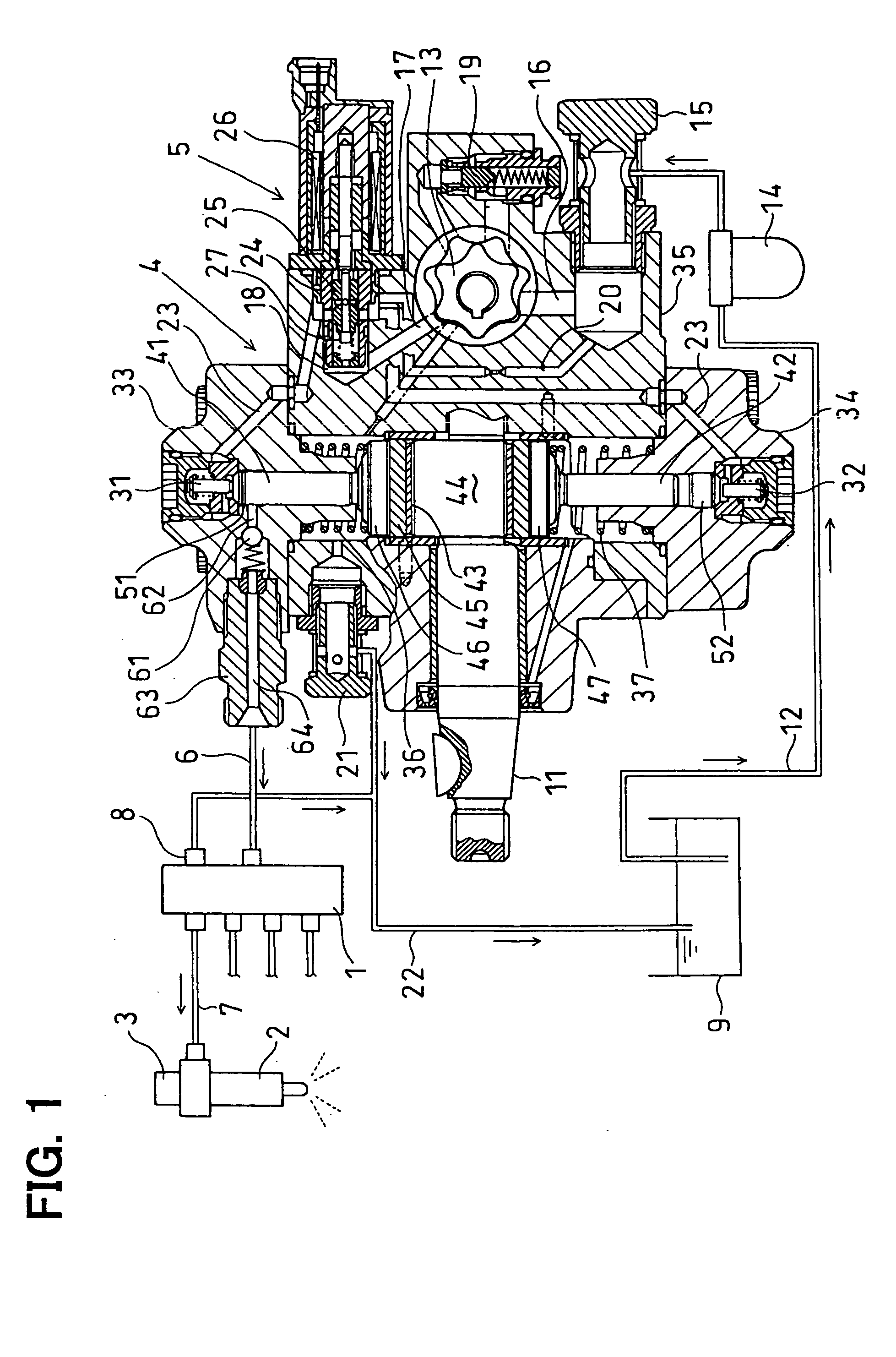
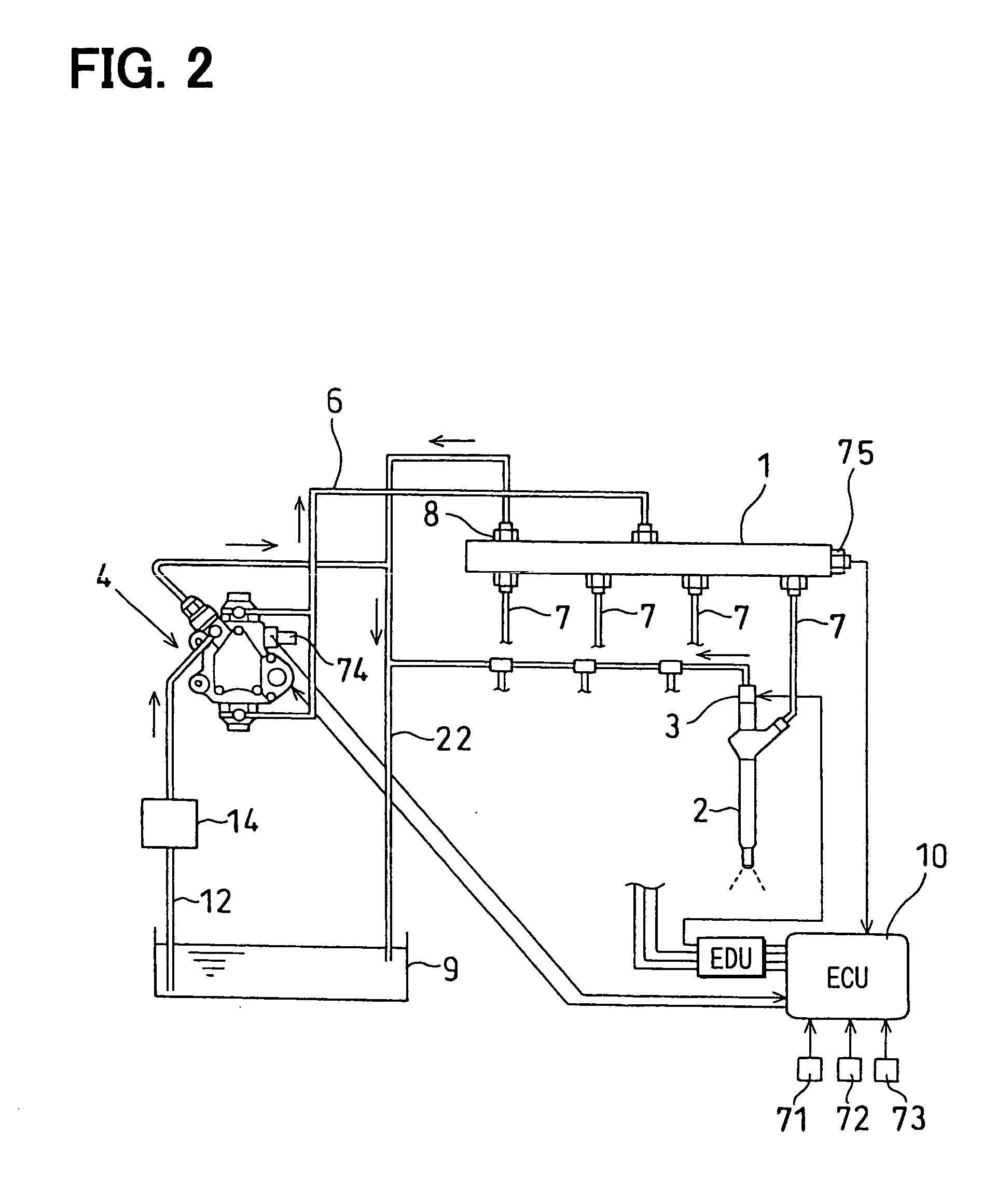
[0052] FIGS. 1 to 13 illustrate the present invention. FIG. 1 shows an entire construction of a supply pump. FIG. 2 shows an entire construction of a common rail type fuel injection system. FIG. 3 is a timing chart showing crank angle, fuel discharge rate, pressure waveform in normal condition, fuel discharge rate, and pressure waveform in inoperative condition of one pressure-supply system.

[0053] A fuel injection system for an internal combustion engine according to the first embodiment is a common rail type fuel injection system (an accumulator type fuel injection system) which is known as a fuel injection system for an internal combustion engine (hereinafter referred to simply as “engine”) such as a multi-cylinder diesel engine mounted on a vehicle, e.g., automobile. It is constructed so that a high-pressure fuel stored within a common rail 1 is injected into combustion chambers of cylinders in the engine through a plurality of injectors (electromagnetic type fuel injection valve...

second embodiment

[0136]FIG. 14 is a flowchart showing a pump discharge quantity troubleshooting method of the present invention. In FIG. 14, the same control processings as in the main routine of FIG. 4 are identified by the same reference numerals and, therefore, explanations thereof will be omitted.

[0137] When the answer in Step S4 is affirmative, i.e., XCND=1, a common rail pressure change in 360° CA period corresponding to the total outflow quantity of fuel flowing out from the plurality of injectors 2 is calculated in a pump pressure-supply period in which at least one of the plurality of pressure-supply systems supplies fuel under pressure. More specifically, the total outflow quantity is multiplied by the bulk modulus E, then the value obtained is divided by the total volume V of the high-pressure fuel portion and the resulting value is assumed to be a common rail pressure change in 360° CA period corresponding to the total outflow quantity (Step S8). Next, a common rail pressure change corre...

third embodiment

[0140]FIGS. 15 and 16 illustrate the present invention. FIG. 15 is a flowchart showing the details of the pump discharge quantity troubleshooting of Step S10 in the main routine of FIG. 14.

[0141] First, an absolute value of a difference between a last-time pump discharge quantity and a this-time pump discharge quantity is calculated. More specifically, an absolute value of a difference between the pump discharge quantity in 360° CA period in a specific pressure-supply system before 360° CA and the pump discharge quantity in 360° CA period in the specific pressure-supply system after 360° CA is calculated. Or, in case of calculating an absolute value with respect to the pump 2 in FIG. 3, an absolute value of a difference between the pump discharge quantity in 360° CA period of the pump 1 and the pump discharge quantity in 360° CA period of the pump 2 is calculated (Step S61).

[0142] Next, first and second decision values (first and second decision thresholds) are calculated based on ...


PUM


Abstract

A fuel injection system for an internal combustion engine includes a fuel supply pump, a fuel pressure detector, and a control unit. The fuel supply pump supplies pressurized fuel to a fuel injection valve in the internal combustion engine. The fuel pressure detector detects the pressure of the fuel supplied. The control unit controls the amount of the fuel supplied based on a deviation between an actual fuel pressure and a target fuel pressure. The control unit includes an integral term calculator and an integral term holder. The integral term calculator adds an integral compensation quantity and a last-time integral term to calculate a this-time integral term based on an integral compensation quantity that is updated according to the deviation. The integral term holder stops the updating of the integral compensation quantity and retains the last-time integral term when a defect in the fuel supply pump is detected.

Description

CROSS REFERENCE TO RELATED APPLICATIONS [0001] This application is based upon and claims the benefit of priority of Japanese Patent Application No. 2003-386428, filed on Nov. 17, 2003, the contents of which are incorporated herein by reference. FIELD OF THE INVENTION [0002] The present invention relates to a fuel injection system for an internal combustion engine and, more particularly, an accumulator-type fuel injection system for highly accurately detecting defects in pump pressure-supply. BACKGROUND OF THE INVENTION [0003] A conventional accumulator-type fuel injection system known as a fuel injection system for an internal combustion engine such as a diesel engine is constructed so as to accumulate a high-pressure fuel within a common rail and inject the fuel to cylinders in the internal combustion engine at a predetermined timing from a plurality of fuel injection valves branched from a common rail. It is necessary that fuel of a high-pressure corresponding to a fuel injection ...

Claims


Application Information

Patent Timeline
Patent Type & Authority Applications(United States)
IPC IPC(8): F02D31/00F02D45/00F02D41/22F02D41/38F02D41/40F02M1/00F02M39/00F02M63/00F02M63/02
CPCF02D41/221F02D41/3845F02D41/408F02D2041/224F02D2041/1409F02M39/005F02M63/0225Y02T10/44F02D41/1401F02D2200/0602Y02T10/40
Inventor UCHIYAMA, KEN
Owner DENSO CORP
Why Eureka
Try Eureka