Power control device and power control method

A power control and power technology, applied in control/regulating systems, instruments, regulating electrical variables, etc., can solve problems such as slowing down interference response and temperature control, and achieve the effects of suppressing flicker, saving man-hours, and preventing deterioration of controllability

Active Publication Date: 2016-07-13
RKC INSTR
View PDF10 Cites 0 Cited by
  • Summary
  • Abstract
  • Description
  • Claims
  • Application Information

AI Technical Summary

Problems solved by technology

In addition, there is a problem that optimum temperature control cannot be performed due to slow disturbance response

Method used


Image

  • Power control device and power control method
  • Power control device and power control method
  • Power control device and power control method

Examples


Embodiment approach 1

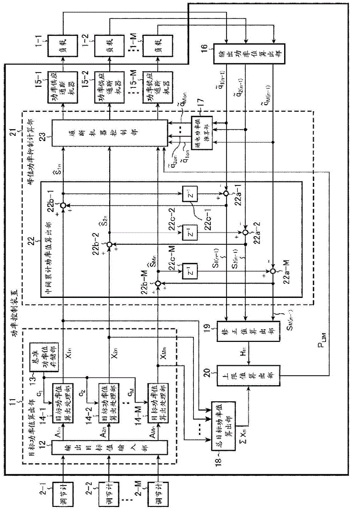
[0049] figure 1 It is a block diagram showing the power control apparatus based on Embodiment 1 of this invention.

[0050] exist figure 1 In the power control device of , an example of controlling the power to be supplied to M (M is an integer of 2 or more) controlled objects in a time-sharing manner has been described.

[0051] which is, figure 1 The power control device is for switching the power supply to the controlled object on / off (power-on / off) every time equivalent to an integral multiple of a half cycle of the power supply waveform (hereinafter, referred to as "unit time"). The power control device that controls the ON), and by controlling the time ratio of the ON time, which is the time when the power is supplied, to the OFF time, which is the time when the power is not supplied, with the operation signal (target value) output from the PID regulator. Proportional power is supplied to the controlled object.

[0052] Hereinafter, the cycle in which the control ...


PUM


Abstract

The present invention can prevent the deterioration of the controllability caused by the change of the total target power value, and can suppress the flicker of the power supply voltage. By the target power value x calculated by the total target power value calculation part (18) 1n ‑x Mn The sum of Σx n Add the correction value H calculated by the correction value calculation unit (19) n , and is set to calculate the power upper limit value P for all loads LIM The upper limit value calculating part (20) of so that corresponding to the target power value x 1n ‑x Mn The sum of Σx n Changes to get the appropriate power upper limit P LIM .

Description

technical field [0001] The present invention relates to a power control device and a power control method for controlling power supplied to a plurality of loads in a time-sharing manner. Background technique [0002] For example, Patent Documents 1 and 2 below disclose a power control device for supplying a power proportional to an operation signal (target value) output from a PID regulator to a load such as a heater. [0003] In this power control device, on / off (power-on / off) for switching the power supply to the load is performed every time equivalent to an integral multiple of a half cycle of the power supply waveform (hereinafter, referred to as "unit time"). ), the power proportional to the operation signal (target value) output from the PID regulator is supplied to the load by controlling the ratio of the power-on time, which is the time when power is supplied, to the off time, which is the time when power is not supplied. supply. [0004] Hereinafter, a power contr...

Claims


Application Information

Patent Timeline
Patent Type & Authority Patents(China)
IPC IPC(8): G05F1/45
CPCY02B70/3225Y04S20/222G05F1/66H02J2310/12H02J3/14
Inventor 后藤茂文秋保启介吉川裕久
Owner RKC INSTR
Why Eureka
Try Eureka