Multi-tube in spiral heat exchanger

a heat exchanger and multi-tube technology, applied in the field of heat exchangers, can solve the problems of affecting the efficiency of heat exchangers, so as to improve the efficiency of heat exchange, enhance heat transfer, and reduce the effect of heat loss

Inactive Publication Date: 2005-05-19
CARRIER CORP
View PDF17 Cites 26 Cited by
  • Summary
  • Abstract
  • Description
  • Claims
  • Application Information

AI Technical Summary

Benefits of technology

[0008] The present invention comprises at least a first thermally conductive tube and a second thermally conductive tube. Each tube is capable of conducting a fluid for use in a heat exchange process. In contrast to other designs, the inventive design intertwines the first tube with the second tube so that the loop of one tube neighbors the loop of the other. In this way, the heat exchanger greatly increases the amount of surface area for heat exchange per linear length of tube so that a more compact design may be achieved. In addition, the spiraling of the tubes together induces turbulence of the fluid within the tubes to enhance heat transfer. Spiraling of the tubes together also ensures close physical contact between the tubes to improve heat exchange. Different fluids may pass through each of the tubes and may be brought together for heat exchange. Because each fluid is contained within its own tube, the fluids do not intermingle during heat exchange. The fluids within each of these tubes are further protected against cross-contamination because the tubes do not share a common wall but, in fact, each have their own wall. In the event of rupture of one wall, fluid may leak but will not intermingle with fluid in the other tube.
[0010] In addition, the tubes may be coiled in such a way as to create a volume within the coils of the tubes. Another heat exchange element may be placed within this volume to augment heat exchange. This additional heat exchange element may spiral in an opposite direction to the spiral of the loops to further improve heat exchange.
[0011] The present invention further comprises a method of manufacturing a multiple tube heat exchanger. In contrast to existing manufacturing techniques, the current technique winds a first heat exchanger tube with at least a second heat exchanger tube about a common axis. Both the first exchanger tube and the second heat exchanger tube have free moving portions that wind about the common axis of rotation in a spiral fashion while the other portions of the heat exchanger tubes are fixed against rotation. In this way, multiple tubes may be wound together and intertwined between the rotationally free portions and the fixed portions of the tube. Consequently, the inventive technique allows for the creation of a tight helical spiral with the first heat exchanger tube intertwined with the second heat exchanger tube.
[0012] A guide may prevent the fixed portions of the tube from winding around the axis of rotation. The guide may be moveable along the axis so as to alter the location of the fixed portions of the tubes. In this way, sections of the tubes may be intertwined and then the guide moved away from the intertwined section of the tubes to allow other sections of the tubes to be intertwined. This guide permits the tubes to be wound evenly together. Another guide may also be used to hold the fixed portions of the tubes in place.

Problems solved by technology

For large capacity systems, these tubes are problematic because the heat exchanger requires a large number of parallel circuits.
As a consequence, the length of the heat exchanger may be very long.
The conventional tube within a tube design poses a risk of water contamination because the tube for one fluid, say water, surrounds the tube of the other heat exchange fluid.
Accordingly, rupture of the inner tube within the larger tube would cause contamination of the water in the larger tube.
However, due to the different geometries of the tubes, the two tubes may have limited areas of physical contact with each other.
Consequently, heat exchange is not very efficient.
The manufacture of this unique heat exchanger presents a challenge as well.
However, the foregoing techniques fail to coil more than one heat exchanging tube in a tight helical spiral as would be best suited for optimum heat transfer.

Method used


Image

  • Multi-tube in spiral heat exchanger
  • Multi-tube in spiral heat exchanger
  • Multi-tube in spiral heat exchanger

Examples


Embodiment Construction

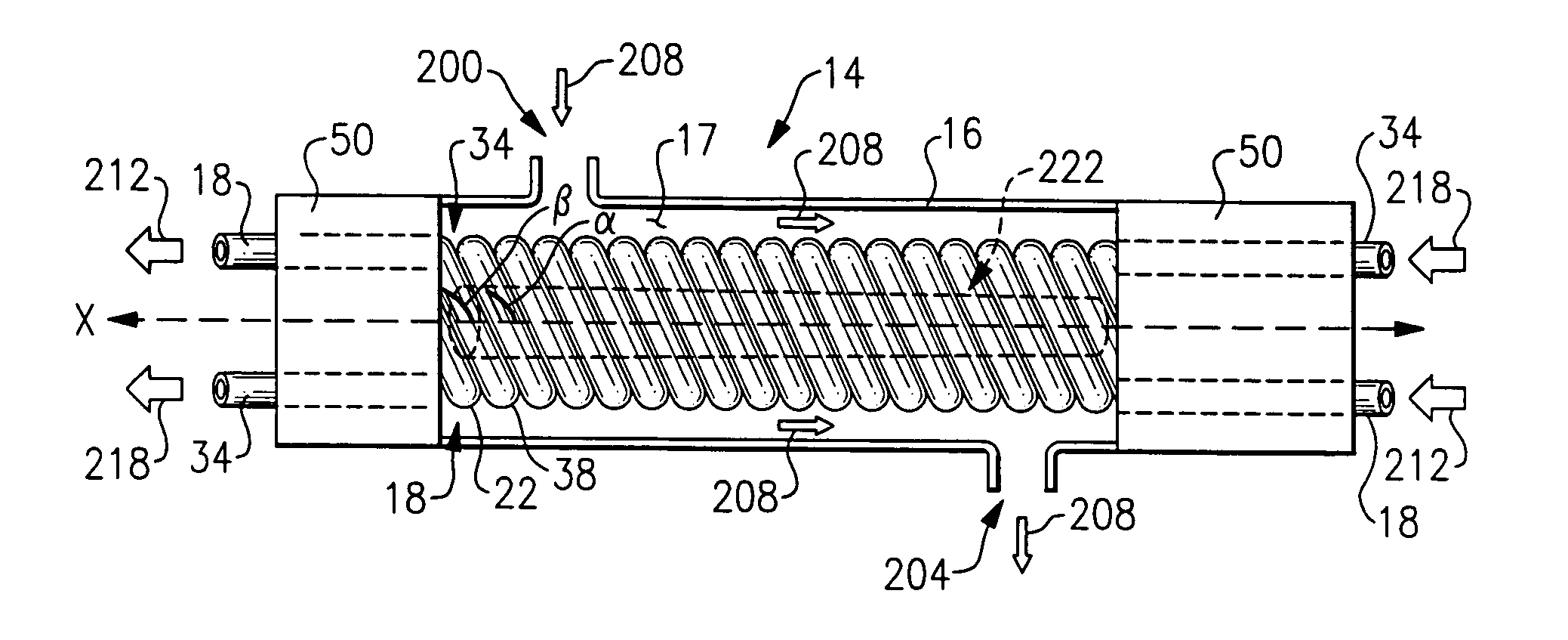
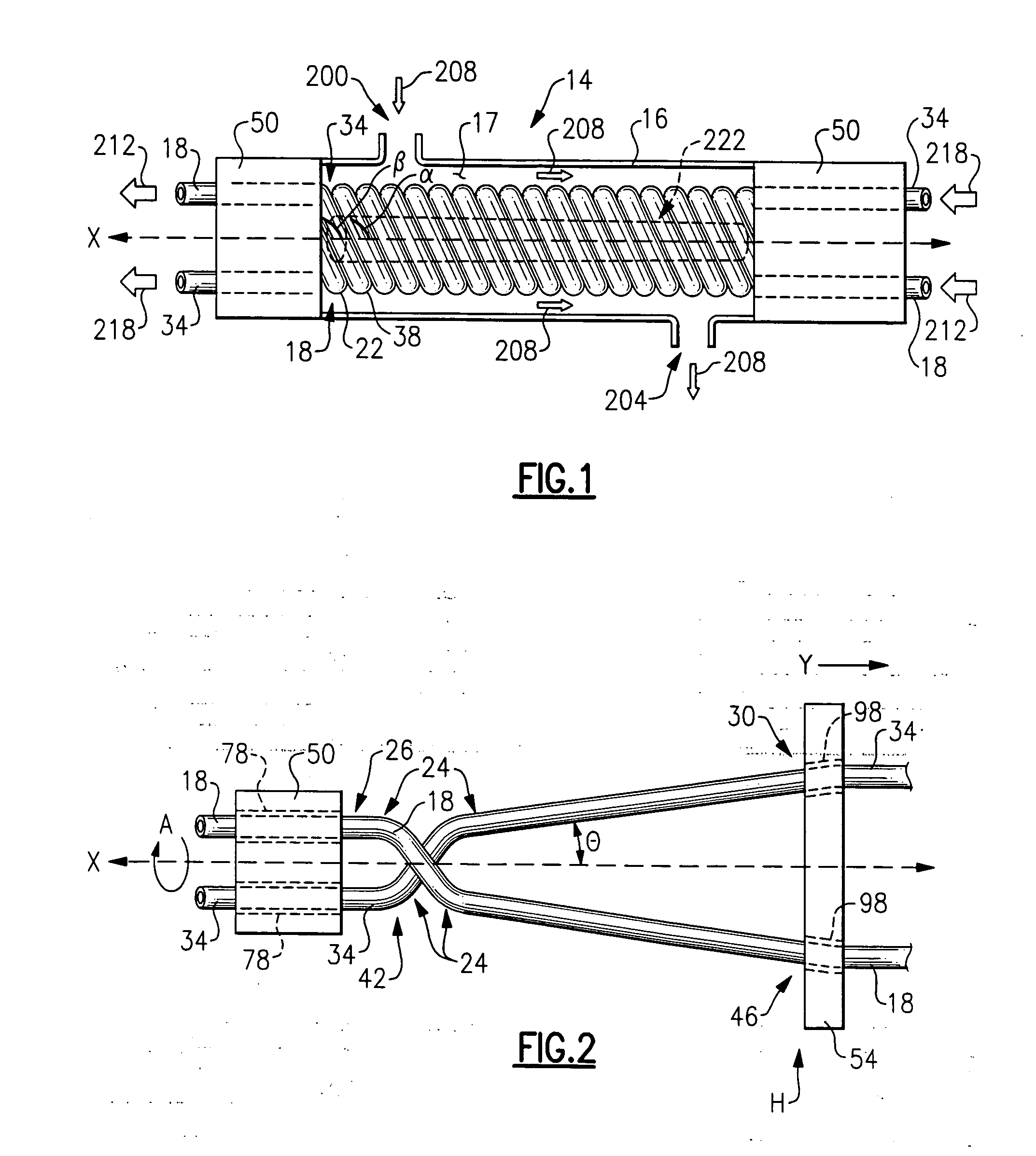
[0028]FIG. 1 illustrates a side cross-sectional view of multiple tube heat exchanger 14. Multiple tube heat exchanger 14 has hollow tube cylinder 16 capped by fixtures 50 to create fluid volume 17 within cylinder 16. Cylinder 16 has first fluid inlet 200 and first fluid outlet 204. Disposed within fluid volume 17 is first thermally conductive heat exchanger tube 18 and second heat exchanger tube 34 intertwined along axis X such that first heat exchanger tube 18 forms first loop 22 that neighbors and preferably contacts second loop 38 of second heat exchanger tube 34 along axis X. Heat exchange between fluids in first heat exchanger tube 18 and second heat exchanger tube is not only enhanced by their contact but also improved due to the spiraling of the tubes 18, 34, which enhances fluid turbulence and therefore heat exchange.

[0029] As shown in FIG. 2, to create the helical intertwining shape of first heat exchanger tube 18 and second heat exchanger tube 34, first heat exchanger tub...


PUM

PropertyMeasurementUnit
thermally conductiveaaaaaaaaaa
angleaaaaaaaaaa
common angleaaaaaaaaaa

Abstract

A heat exchanger has a first thermally conductive tube for conducting a fluid and a second thermal conductive tube for conducting a fluid. The first thermally conductive tube forms a first loop while the second thermally conductive tube forms a second loop. The first loop neighbors the second loop.

Description

BACKGROUND OF THE INVENTION [0001] This invention relates to a heat exchanger. [0002] A heat exchanger is commonly used for refrigeration, cooling, and heating applications. For these applications, the heat exchanger transfers heat from one fluid to another fluid without the fluids intermingling. The fluid may be a gas or a liquid. For certain high-pressure applications involving CO2 gas, manufacturers have used a tube-in-tube design for a heat exchanger. Essentially, the heat exchanger is one tube containing one fluid surrounded by another larger tube containing the other fluid. For example, CO2 gas may circulate within the inner tube while water may circulate in the surrounding tube. Heat is exchanged through the surface of the inner tube. [0003] For a high-pressure application, tube diameters have to be kept small (less than ⅜ of an inch) to maintain a reasonable wall thickness. For large capacity systems, these tubes are problematic because the heat exchanger requires a large nu...

Claims


Application Information

Patent Timeline
Patent Type & Authority Applications(United States)
IPC IPC(8): F28D7/00F28D7/02
CPCF28D7/022F28D7/0008F28F2265/16B21D53/06B21D11/06B21D11/14B23P15/26
Inventor PARK, YOUNG KYUWINCH, GARY D.RIOUX, WILLIAM A.
Owner CARRIER CORP
Why Eureka
Try Eureka