Micro liquid control system

a liquid control system and liquid control technology, applied in the field of micro liquid control system, can solve the problems of large quantity processing, slow response time, slow transport speed, etc., and achieve the effect of large quantity processing and high speed

Inactive Publication Date: 2005-05-19
AISIN SEIKI KK
View PDF10 Cites 88 Cited by
  • Summary
  • Abstract
  • Description
  • Claims
  • Application Information

AI Technical Summary

Benefits of technology

[0011] The present invention is made by taking the above-described situation into consideration. The objective of the present invention is to propose a micro

Problems solved by technology

Also it does not transport the droplets as a liquid flow, but, since the droplets are transported with electrostatic force, a transportation speed is slow and it is not suitable for a high speed, large quantity processing.
But, since it utilizes chemical phase changes from sol to gel and from gel to sol, the response time is slow and it is not suitable for high speed, large quantity processing.
And, as it forms a closing valve using the phase change from sol to g

Method used


Image

  • Micro liquid control system
  • Micro liquid control system
  • Micro liquid control system

Examples


first embodiment

1. First Embodiment

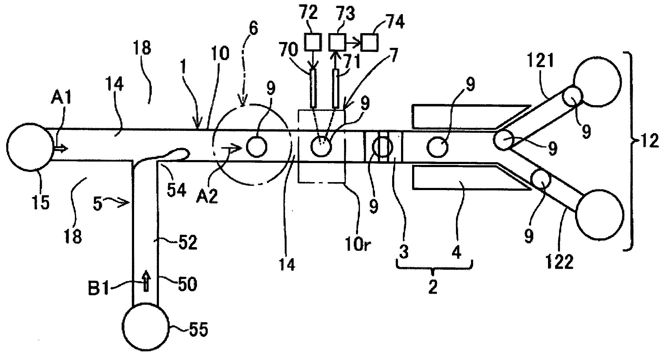
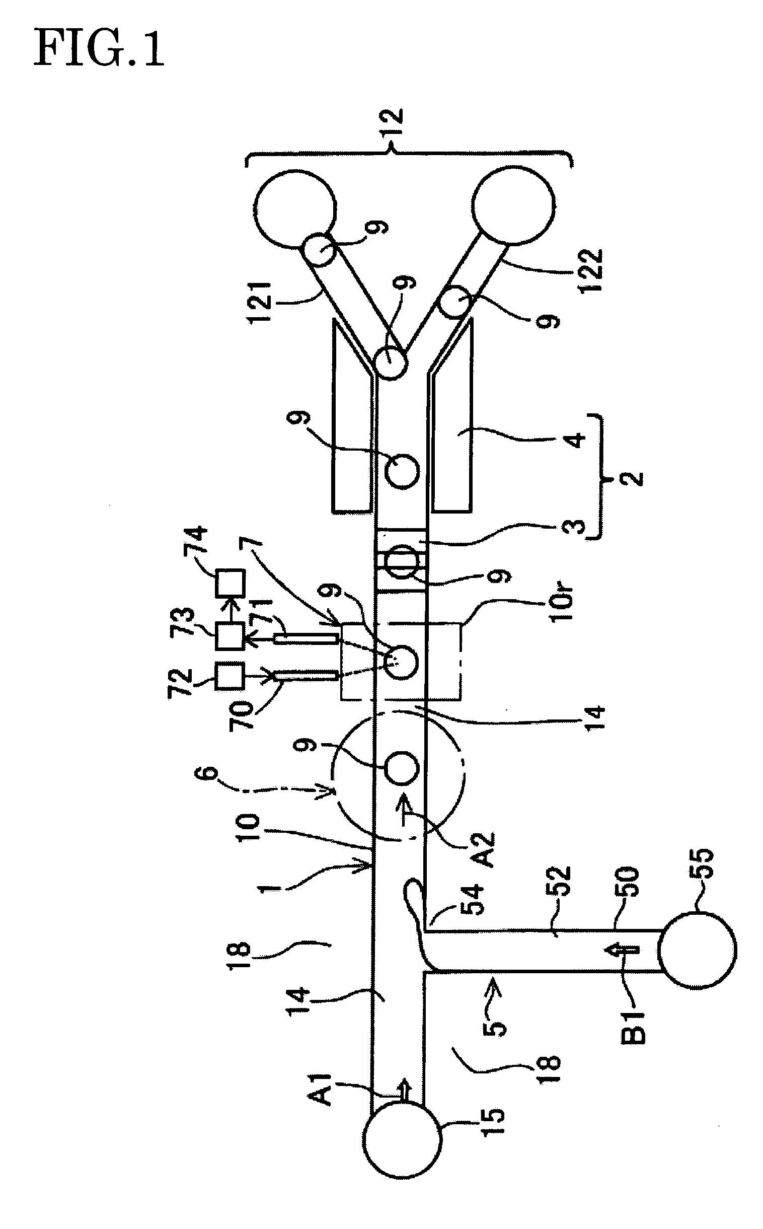
[0033]FIG. 1 shows the first embodiment. As shown in FIG. 1, according to a micro liquid control system, a microchannel 1 is provided on a transparent substrate 18 made of resin or glass. The microchannel 1 comprises a main channel 10 which flows a main liquid 14 wherein small size droplets 9 (target object) as a small target object are dispersed and a sorting channel 12 which is provided at the downstream side of the main channel 10 and sorts the target object. At the upstream side of the main channel 10, a pump 15 which discharges the main liquid 14 to the microchannel 1 is provided as a first source. The sorting channel 12 has a Y branch at the downstream side of the main channel 10 to form a first sorting channel 121 and a second sorting channel 122. Also a droplet selecting means 2 (target object selecting means) is provided which selects the droplets 9 which flow in the microchannel and supplies them to the sorting channel 12.

[0034] Further, according to th...

second embodiment

2. Second Embodiment

[0056]

[0057]FIGS. 5 and 6 show the second embodiment. Also, in this embodiment, in a manner similar to the first embodiment shown in FIG. 1, a droplet forming means 5, a droplet counting part 6 and an information detecting part 7 are provided at the upstream side of a main channel 10 of a microchannel 1. Since the configuration and its function are the same as those of the embodiment 1, the description and the figure will not be repeated here. The common part has basically the common reference numeral.

[0058] According to a micro liquid control system of this embodiment, as shown in FIG. 5, the microchannel 1 comprises the main channel 10 to flow a main liquid 14 in which a fine size droplet 9 is dispersed and a sorting channel 12 which sorts the droplet 9 at the downstream side of the main channel 10. The sorting channel 12 has a Y branch at the downstream side of the main channel 10 and comprises a first sorting channel 121 and a second sorting channel 122. In ...

third embodiment

3. Third Embodiment

[0068]FIGS. 7 and 8 show the third embodiment. Also, in this embodiment, in a manner similar to the first embodiment as shown in FIG. 1, a droplet forming means 5, a droplet counting part 6 and an information detecting part 7 are provided at the upstream side of a main channel 10 of a microchannel 1. As the configuration and its function are the same as those of the embodiment 1, the description and the figure will not be repeated here. The common part has basically the common reference numeral.

[0069] According to a micro liquid control system related to the present embodiment, as shown in FIG. 7, the microchannel 1 comprises the main channel 10 to flow a main liquid 14 in which a fine size droplet 9 is dispersed and a sorting channel 12 which sorts the droplet 9 at the downstream side of the main channel 10.

[0070] The sorting channel 12 has a Y branch at the downstream side of the main channel 10 and comprises a first sorting channel 121 and a second sorting ch...


PUM


Abstract

The present invention provides a micro liquid control system which, adopting a method to flow a fine target object such as droplets together with a main liquid, allows high speed, large quantity processing for sorting the target object such as the droplets. The system comprises a microchannel, which includes a main channel to flow the main liquid in which the fine target object is dispersed and a sorting channel to sort the target object at the downstream side of the main channel, and a target object selecting means, which selects the target object flowing in the microchannel and supply it to the sorting channel. The target object selecting means comprises electrodes on which the voltage of the same polarity or the opposite polarity is applied to move and select the target object with the attractive or repulsive force.

Description

CROSS REFERENCE TO RELATED APPLICATION [0001] This application is based on and claims priority under 35 U.S.C. §119 to Japanese Patent Application 2003-389447, filed on Nov. 19, 2003, the entire content of which is incorporated herein by reference. BACKGROUND OF THE INVENTION [0002] 1 Field of the Invention [0003] This invention relates to a micro liquid control system which selects a target object such as a droplet etc. [0004] 2. Description of the Related Art [0005] Japanese Patent Application Laid-Open No. H10(1998)-267801 (hereinafter referred to the Patent document 1) discloses a handling apparatus of fine liquid particles wherein a plurality of electrodes are arranged to form an electrode array on a substrate; droplets of agents and specimen are formed; the droplets are put on the hydrophobic surface; transporting of the droplets is preformed by electrostatic force with the voltage application in sequence to the electrode array. The surround of the droplet is not liquid phase ...

Claims


Application Information

Patent Timeline
IPC IPC(8): B01L3/00B01L3/02B03C9/00G01N15/14
CPCB01L3/0241B01L3/502761B01L3/502784B01L2200/061B01L2200/0673G01N2015/149B01L2400/0415B03C9/00G01N15/1459G01N15/1484B01L2300/0864
Inventor KAWANO, TAKASHIKANAI, NARITOSHIYAMAMOTO, MASANORI
Owner AISIN SEIKI KK
Why Eureka
Try Eureka