
Jam tolerant electromechanical actuation systems and methods of operation

Active Publication Date: 2005-05-19
PARKER INTANGIBLES LLC
View PDF21 Cites 53 Cited by
  • Summary
  • Abstract
  • Description
  • Claims
  • Application Information

AI Technical Summary

Benefits of technology

[0011] Specifically, in an aircraft, having a fixed supporting structure and a control surface movable relative thereto, a jam tolerant actuating system including a computer, control means and at least two electromechanical actuator assemblies, each of the actuator assemblies further including a main motor for providing motion force therefore; a load sensor and a position sensor on the actuator assembly; a coupling/decoupling mechanism, positioned at the output member of the actuator assembly, for severing the load path between the actuator assembly and the movable surface; and a disconnect actuator for providing motive force for the coupling/decoupling mechanism, a method for controlling the actuating system, comprising the steps of: operating the movable control surface by the actuator assembly via the main motor, as directed by the computer via Conmmand and Power inputs through the control means; relaying, from the control means to the computer, a plurality of the following inputs; i. main motor speed from a main motor commutator; ii. main motor current; iii. actuator assembly output

Problems solved by technology

Furthermore, this structure cannot be reconnected while the system is loaded or in motion.
This feature does not allow the system to continue operating after a failure.
However, the Reilly disconnection is triggered by an overload of the input shaft.
As already noted, an actuator failure may not always manifest itself as an overload and thus the Reilly design would not be tolerant of other types of failure.
Frangible elements cannot be tested prior to use.

Method used


Image

  • Jam tolerant electromechanical actuation systems and methods of operation
  • Jam tolerant electromechanical actuation systems and methods of operation
  • Jam tolerant electromechanical actuation systems and methods of operation

Examples


Embodiment Construction

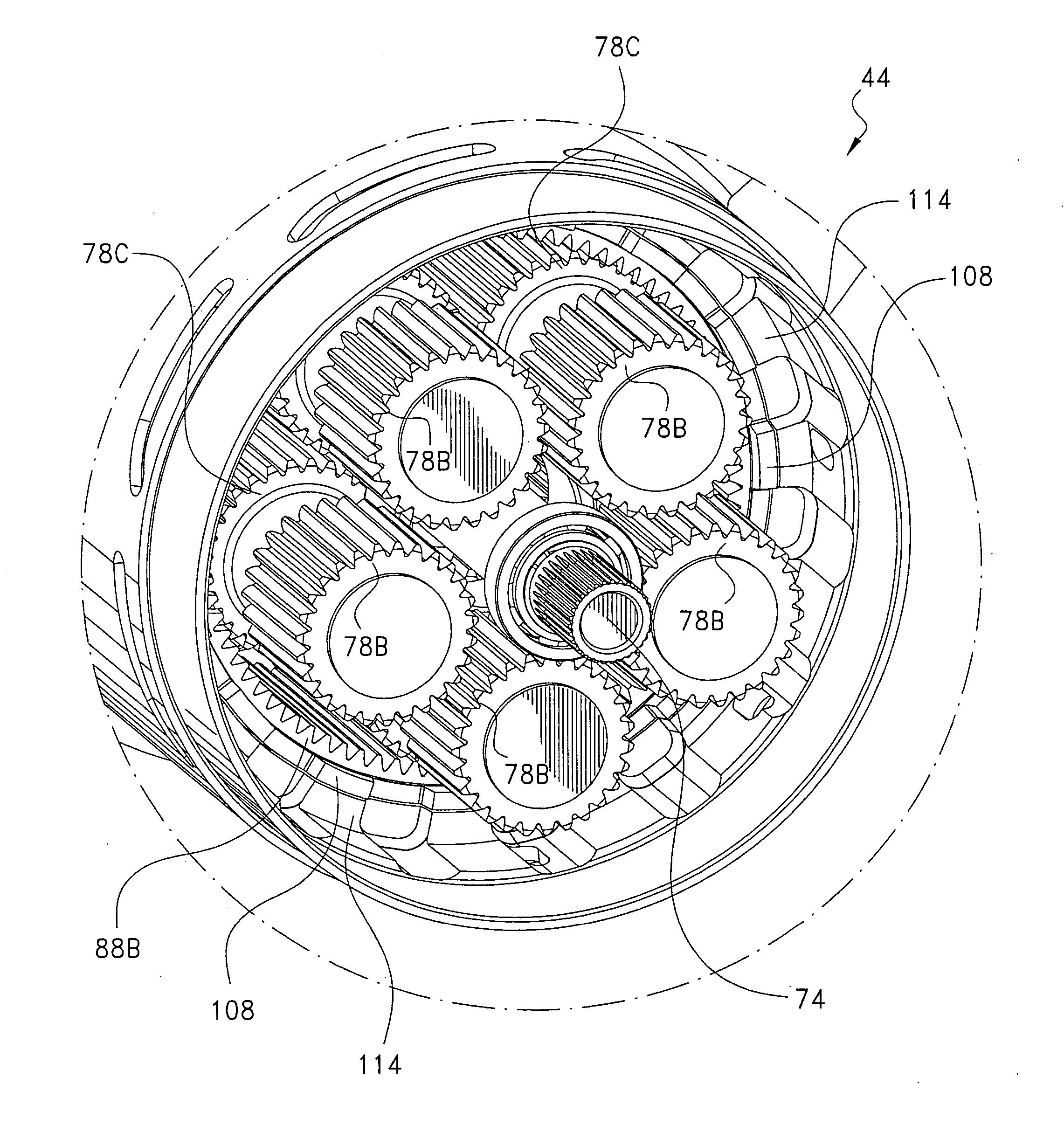
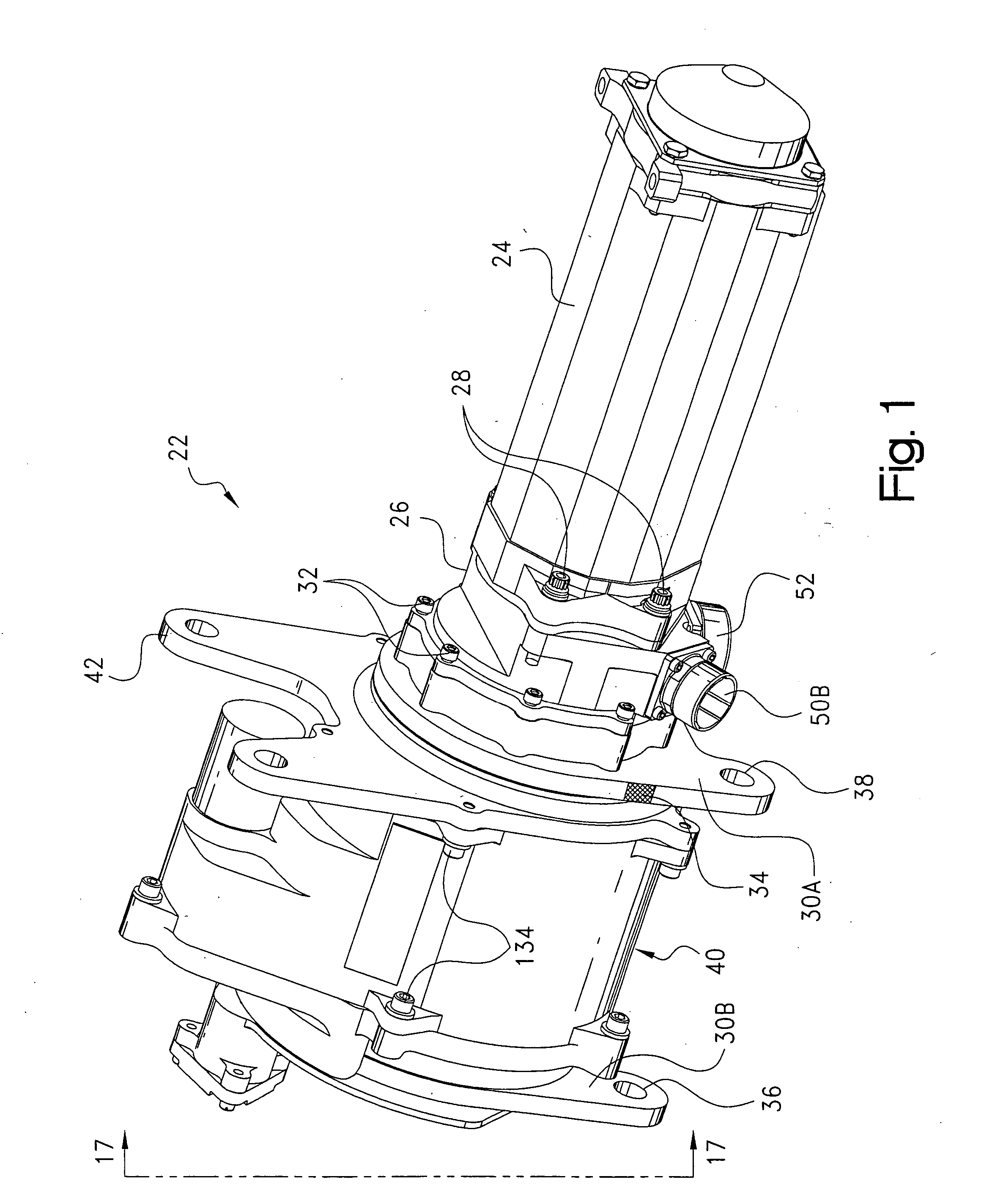
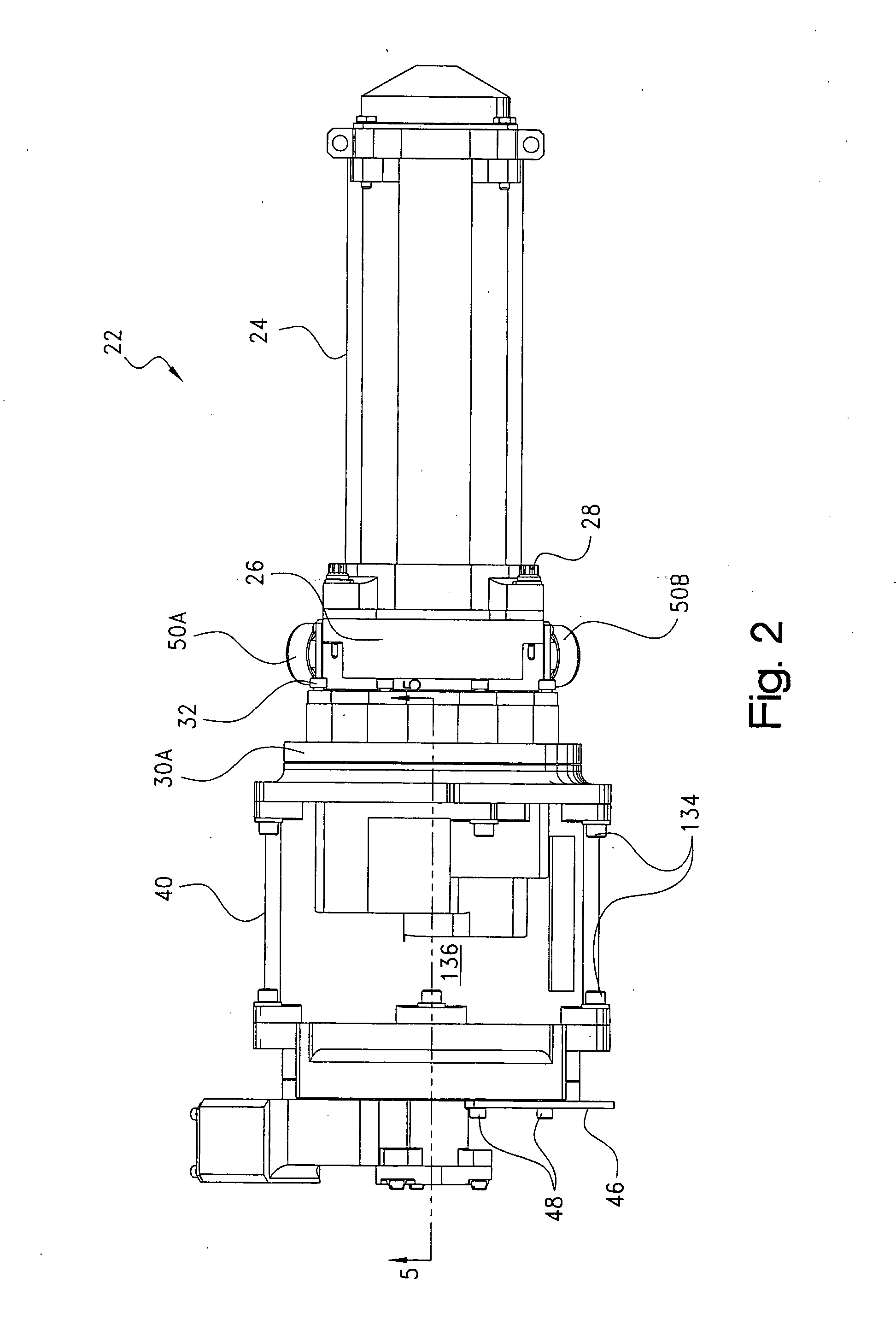
[0061] Referring now to the drawings wherein like numerals are used throughout the several views to designate like parts, and more particularly to FIGS. 1, 2, 3 and 18, illustrated therein is an electromechanical geared rotary actuator (GRA), generally designated by reference numeral 22, suitable for use, for example, in single and / or multiple jam-resistant electromechanical actuating systems, such as single unit actuator system 20, shown in FIG. 18. GRA 22, which is utilized, for example, for primary or secondary flight surface control, includes, as best seen in FIGS. 1 and 18, an input power source, such as a bidirectionally rotatable prime mover or mechanical power source, such as electric motor 24, the proximate end of which is fixedly secured, via a plurality of bolts 28, to a connector housing 26, which in turn is connected, via a plurality of further bolts 32, to grounded housing structures 30a, 30b, that include axially-spaced, separate, front and rear end flange portions 36...


PUM


Abstract

In a vehicle, having a fixed supporting structure and a load movable relative thereto, a jam tolerant actuating system, a method for controlling this system including: Locating a physical coupling / decoupling mechanism between the load and an actuator assembly as close a practicable to the load; constructing the coupling / uncoupling mechanism to be reversible, and hence testable; and controlling the connection / disconnection via decision making electronics which will detect any system failure by monitoring, at a minimum: actuator main motor load and speed, and actuator output load. Also set forth are specific embodiments of pivotable rotary geared actuators as well as linear ball screw type actuators embodying the coupling / uncoupling mechanisms of this invention.

Description

CROSS-REFERENCE TO RELATED CASES [0001] The present application claims the benefit of the filing date of U.S. Provisional Application Ser. No. 60 / 511,506, filed Oct. 15, 2003, the disclosure of which is incorporated herein by reference.FIELD OF THE INVENTION [0002] The present invention pertains to jam tolerant electromechanically operated actuation systems, of both the rotary and linear types, together with their methods of operation that can be universally utilized wherever such actuation systems are required, e.g., in vehicles, etc. Specifically, this invention pertains to electrical jam-detection systems and associated locking devices that can be electrically engaged and disengaged that do not require an overload to relieve the jam and that are testable since the process is completely reversible. BACKGROUND OF THE INVENTION [0003] One of the applications of the jam tolerant electromechanical actuation systems of this invention, among others, is for the actuation of thin wing sta...

Claims


Application Information

Patent Timeline
IPC IPC(8): B64C13/24B64C13/42B64C13/50B64C39/00F16H25/20F16H35/10F16H57/02H02K7/116
CPCB64C13/24B64C13/42B64C13/50F16H2057/0081F16H35/10F16H2025/2071H02K7/116F16H25/20B64C13/505
Inventor FLATT, JAMES E.
Owner PARKER INTANGIBLES LLC
Learn More