
Pilot director light utilizing light emitting diode (LED) technology

a technology of light-emitting diodes and pilot lights, which is applied in the direction of traffic control systems, instruments, transportation and packaging, etc., can solve the problems of long operational life and low power dissipation, and achieve the effect of generating less heat and dissipation of low power

Active Publication Date: 2005-05-19
HONEYWELL INT INC
View PDF12 Cites 18 Cited by
  • Summary
  • Abstract
  • Description
  • Claims
  • Application Information

AI Technical Summary

Benefits of technology

[0009] Accordingly, the PDLs in exemplary embodiments of the present invention do not require tinted or prismatic lenses to generate light at a specific color and in a specific direction. Thus, light may be illuminated at a higher efficiency. Also, the LED light sources may provide a longer operational life, resulting in less frequent burn-outs and replacements.
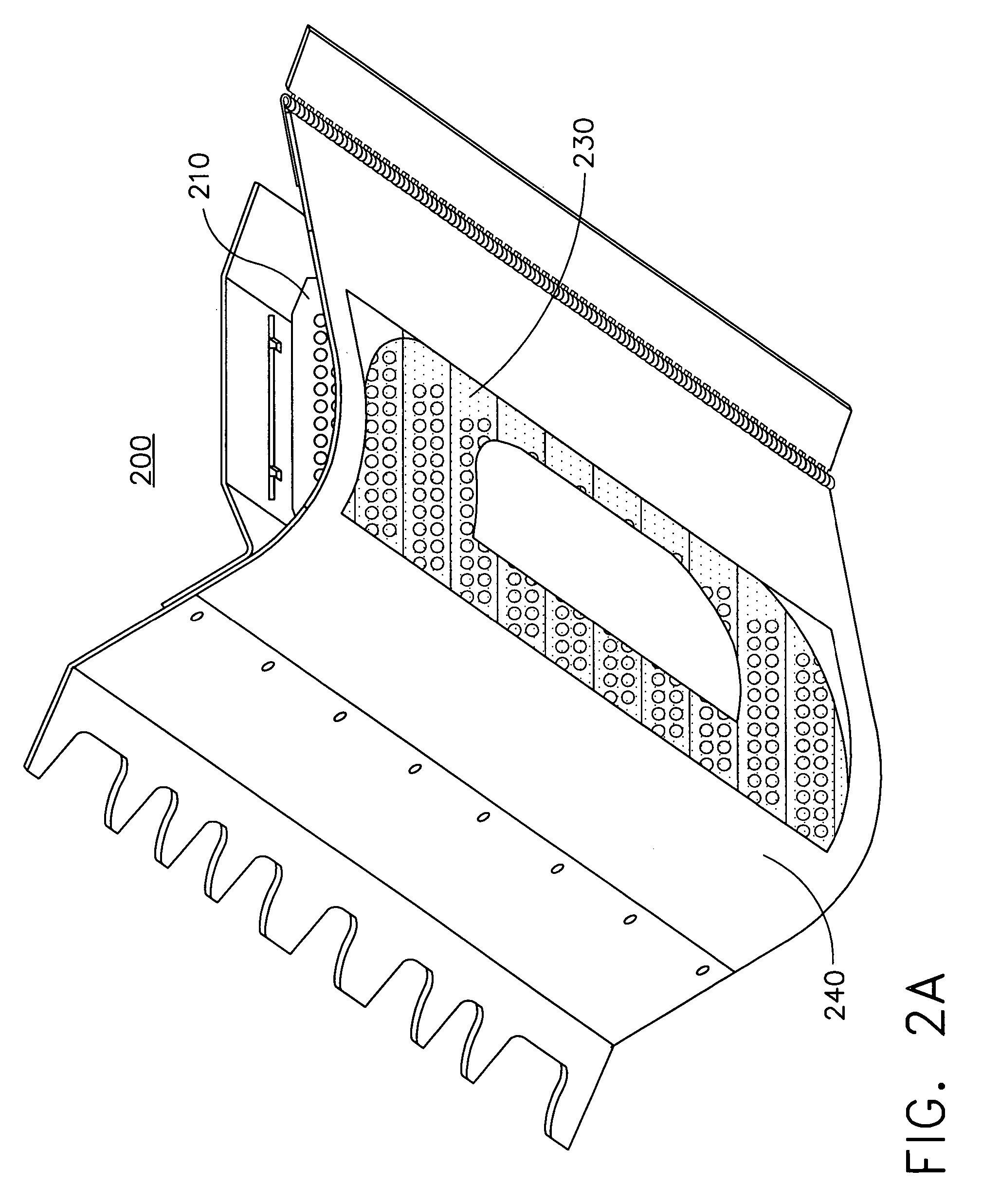
[0012] According to an exemplary embodiment, each light emitting device is comprised of a plurality of LED banks, each bank including multiple subsets of LEDs, thereby providing a high degree of redundancy. As such, a burn-out of a single LED will only effect the operation of the subset of LEDs to which it is connected, and therefore may not significantly affect the readability of the symbol or pattern being illuminated by the corresponding light-emitting device.

Problems solved by technology

Furthermore, the LED light sources may be configured to dissipate a low amount of power and generating less heat, as compared to incandescent light sources.
Also, the LED light sources may provide a longer operational life, resulting in less frequent burn-outs and replacements.

Method used


Image

  • Pilot director light utilizing light emitting diode (LED) technology
  • Pilot director light utilizing light emitting diode (LED) technology
  • Pilot director light utilizing light emitting diode (LED) technology

Examples


Embodiment Construction

[0027] Exemplary embodiments of the present invention are disclosed in the following description.

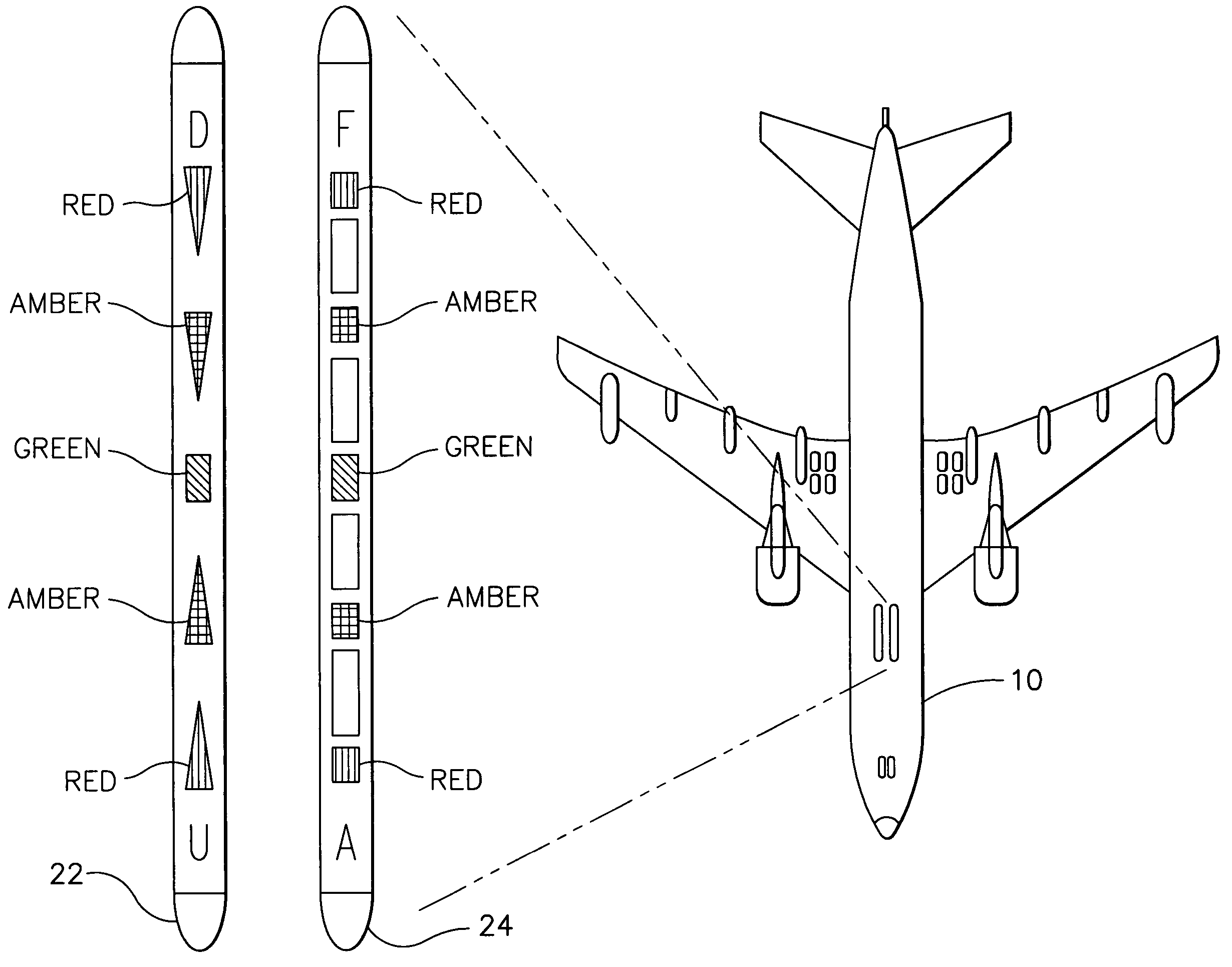
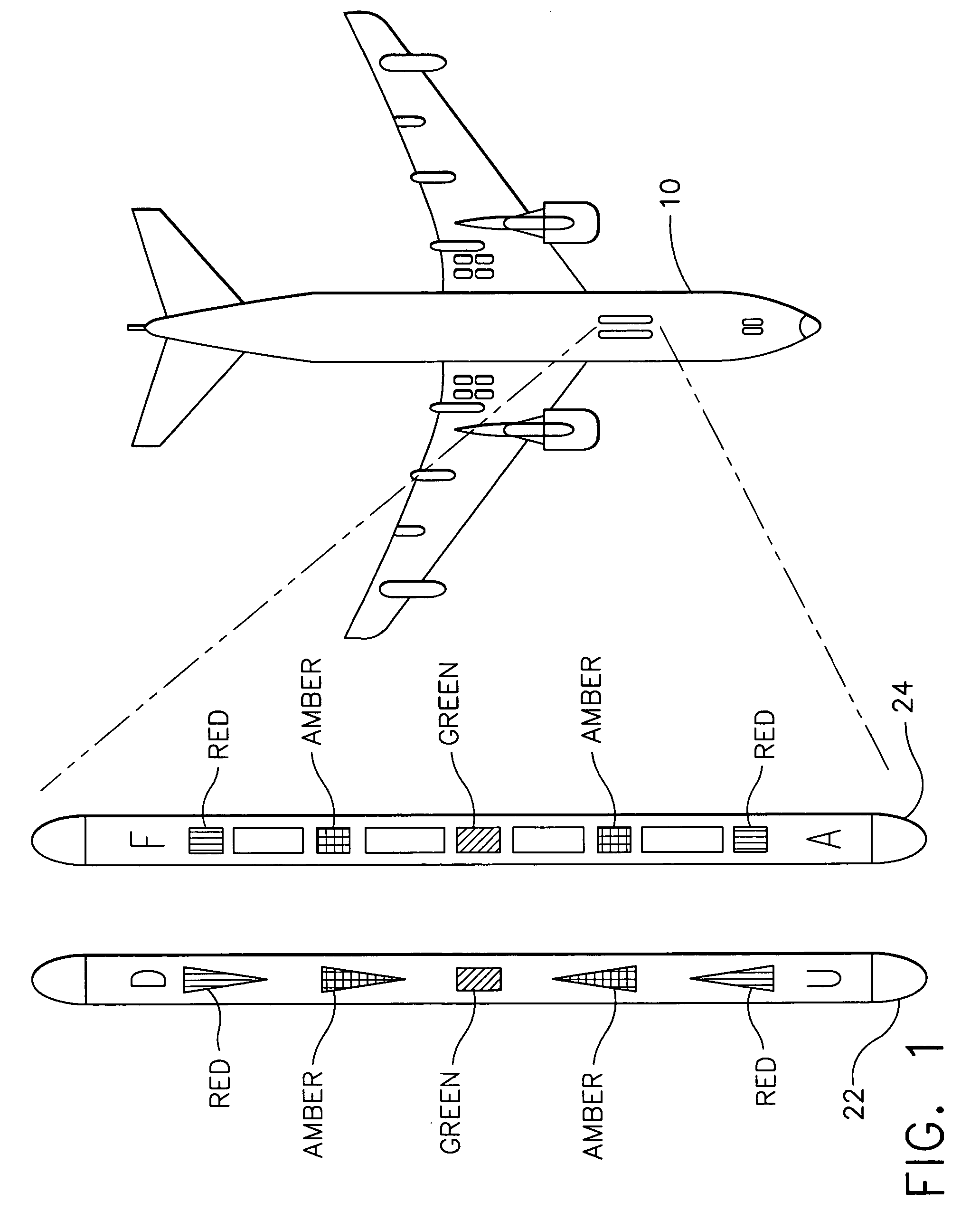
[0028] The present invention is directed to Pilot Director Lights (PDLs) on the exterior of a refueling tanker aircraft, which utilize light emitting diodes (LEDs) as a light source. FIGS. 9 and 10 illustrate a side view and upward view, respectively, of the implementation of PDLs on the exterior of a refueling tanker aircraft 10 for use in conducting the refueling of an approaching aircraft 30. As shown in FIG. 10, the PDLs may be implemented as two rows of lights 122 and 124, which are operable to illuminate symbols and patterns similar to those in light arrays 22 and 24 illustrated in FIG. 1. For example, row 122 may be used for providing information to the pilot of the approaching aircraft 30 as to the elevational (vertical) position of aircraft 30 with respect to an optimum position for performing the refueling operation. Also, row 124 may be configured to provide fore-aft position...


PUM


Abstract

Pilot Director Lights (PDLs) mounted on the exterior of a refueling tanker aircraft (10) utilize light emitting diodes (LEDs) (213) as a light source to provide visual information to the pilot of an approaching aircraft (30). The PDLs may include a plurality of light emitting devices (200) arranged in arrays (123 and 124), each light emitting device (200) being configured to illuminate a particular symbol / pattern. Each light emitting device (200) may include a plurality of modular banks (210) of LEDs (213), which are configured to emit light through a clear lens (230) within a particular field of view. The PDL arrays (123 and 124) may provide visual feedback regarding the elevational and fore-aft position of the approaching aircraft (30) relative to the boom envelope (14) of the tanker aircraft (10).

Description

FIELD OF THE INVENTION [0001] The present invention is directed to Pilot Director Lights (PDLs) mounted on a refueling tanker aircraft, and more particularly, to PDLs including one or more light emitting diodes (LEDs) as a light source. BACKGROUND OF THE INVENTION [0002] Pilot Director Lights (PDLs) generally consist of rows of lights mounted on the exterior of a refueling tanker aircraft for providing information to the pilot of an approaching aircraft to prepare for and maintain refueling boom engagement. Such lights may include lenses whose shapes or masking correspond to symbols or patterns to be illuminated to the approaching pilot. [0003] PDLs are used for providing positional and operational feedback in order to help the approaching pilot prepare for and maintain contact between the refueling boom nozzle and a fuel receptacle of the receiving aircraft. For example, PDLs may provide information as to the elevational (vertical), telescoping (fore-aft) and lateral (azimuthal) po...

Claims


Application Information

Patent Timeline
Patent Type & Authority Applications(United States)
IPC IPC(8): B64D39/00B64D47/06H01L33/00H01L33/58
CPCB64C2027/8236B64D2203/00B64D47/06B64D39/00
Inventor BUTSCH, STEVE M.SINGER, JEFFREY M.BERGER, VALERIY
Owner HONEYWELL INT INC
Learn More