Sheet take-out apparatus
- Summary
- Abstract
- Description
- Claims
- Application Information
AI Technical Summary
Benefits of technology
Problems solved by technology
Method used
Image
Examples
operation example 1
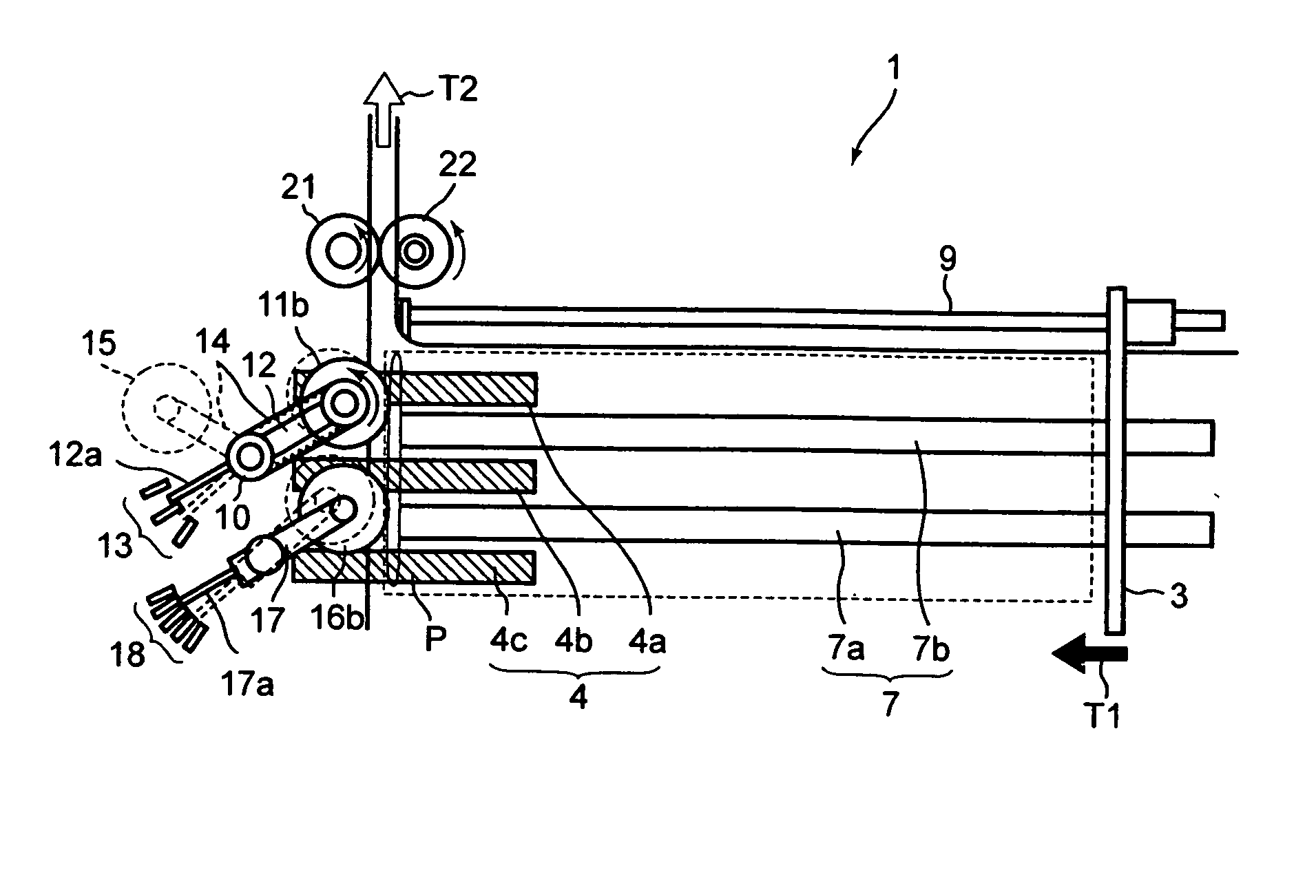
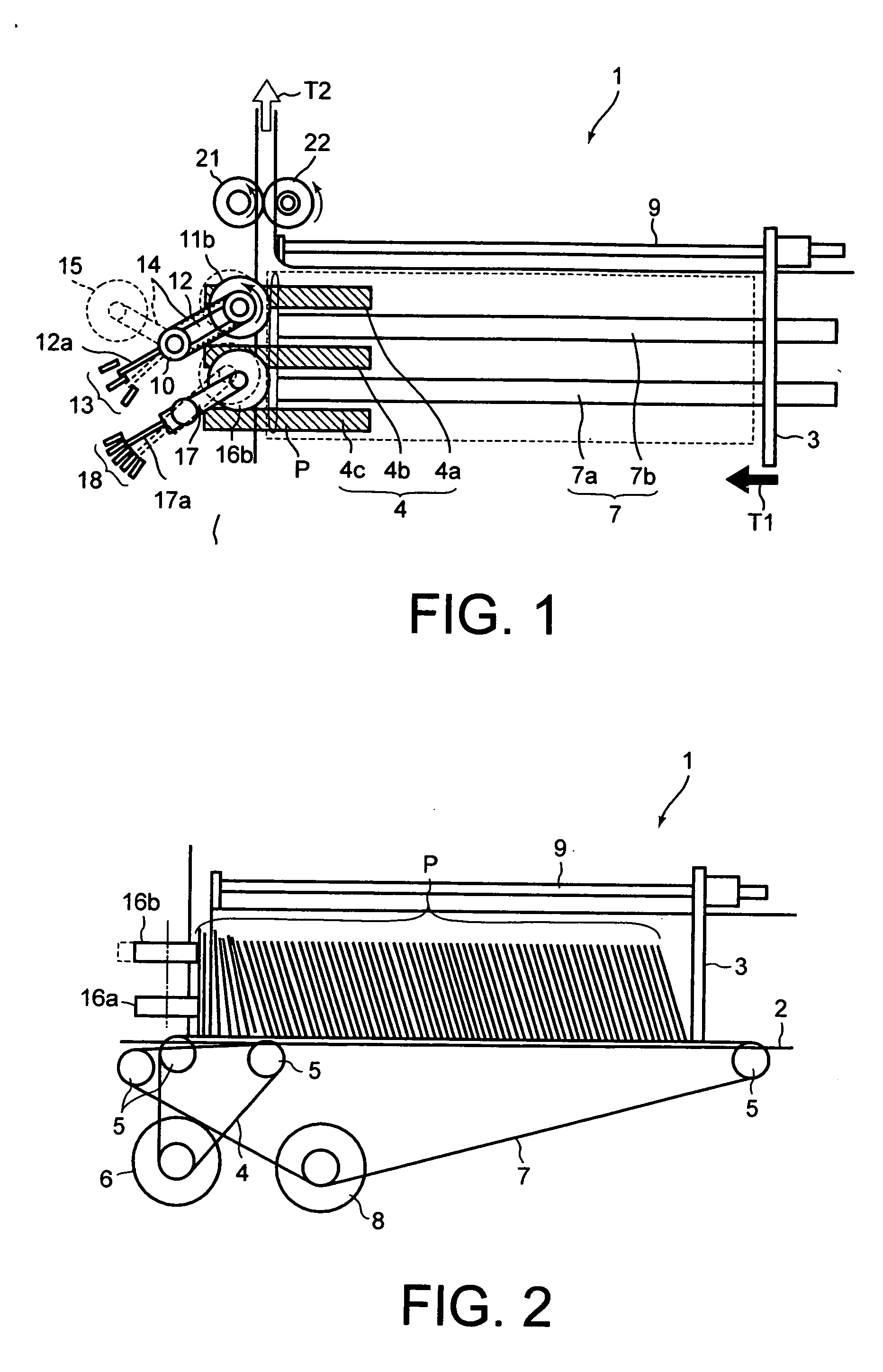
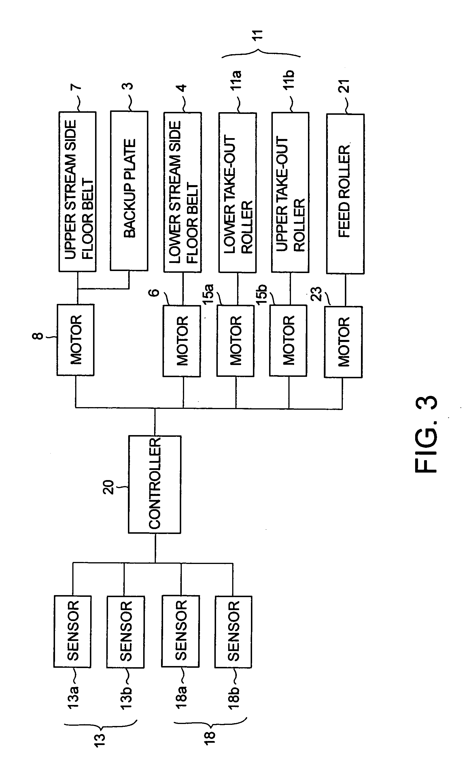
[0052] When the tolerance of the take-out position in the conveying direction where postal matter P can be stably taken out is assumed as buffer B, the moving speeds of floor belts 4 and 7 can be expressed as a function of buffer B, the projection position of each of rollers 11a, 11b, 16a, and 16b respectively detected via sensors 13a, 13b, 18a, and 18b mentioned above, and processing speed K [sheets / h] of take-out apparatus 1. Further, assuming the projection position of each of take-out rollers 11a and 11b detected via sensors 13a and 13b as P1, the projection position of each of auxiliary rollers 16a and 16b detected via sensors 18a and 18b as P2, and the tilt angle of postal matter P supplied to the take-out position as L, the moving speed functions of floor belts 4 and 7 are expressed by the following formulas (1) to (3).
V1=f(L, V2) (1)
V2=f(B, K) (2)
B=f(P1, P2, L) (3)
[0053] When controlling V1 and V2 on the basis of the formulas (1) to (3) and grouping possible cases, a ...
operation example 2
[0064] Here, it is premised to guide a user by handling precautions and serviceman's explanation so as to preset postal matter P in a forward falling state (the state shown in FIG. 4) in take-out apparatus 1 and control not to set postal matter P in a backward falling state (the state shown in FIG. 5) and in an upright state. Further, on the assumption of such control, moving speed V1 of lower-stream side floor belt 4 is not made lower than moving speed V2 of upstream side floor belt 7. Namely, postal matter P is all set in a forward falling state, so that a case of an occurrence of backward falling may not be considered. On the other hand, as explained in operation example 1, when correcting the posture of backward falling, there is the possibility that according to the state of postal matter P, the take-out operation by take-out roller 11 may be stopped temporarily. However, in operation example 2, it is not required, so that the reduction in the processing speed due to the tempor...
operation example 3
[0067] Here, the projection positions of two take-out rollers 11a and 11b are detected by sensors 13a and 13b and the falling state of postal matter P is detected by take-out roller 11. Therefore, the posture of postal matter P is detected at four locations of two take-out rollers 11a and 11b and two auxiliary rollers 16a and 16b in total as a projection position of each roller and all the postures of postal matter P can be detected accurately.
[0068] In this case, the control operation by take-out apparatus 1 can be explained basically by adding detection angle Lp by take-out roller 11 to the relational expression in operation example 1 mentioned above. The functions at this time are expressed by the following formulas (4) to (6).
V1=f(L, Lp, V2) (4)
V2=f(B, K) (5)
B=f(P1, P2, L, Lp) (6)
[0069] Further, a control table at this time can be obtained by adding Lp to the table of operation example 1 mentioned above. The control table in operation example 3 is shown in Tables 3a and ...
PUM
| Property | Measurement | Unit |
|---|---|---|
| Speed | aaaaa | aaaaa |
Abstract
Description
Claims
Application Information
 - R&D
- Intellectual Property
- Life Sciences
- Materials
- Tech Scout
- Unparalleled Data Quality
- Higher Quality Content
- 60% Fewer Hallucinations
Browse by: Latest US Patents, China's latest patents, Technical Efficacy Thesaurus, Application Domain, Technology Topic, Popular Technical Reports.
© 2025 PatSnap. All rights reserved.Legal|Privacy policy|Modern Slavery Act Transparency Statement|Sitemap|About US| Contact US: help@patsnap.com


