Collision detection sensor for vehicle and collision detection device for vehicle

Inactive Publication Date: 2005-05-19
HONDA MOTOR CO LTD
View PDF4 Cites 29 Cited by
  • Summary
  • Abstract
  • Description
  • Claims
  • Application Information

AI Technical Summary

Benefits of technology

[0017] According to the collision detection device for a vehicle, since it includes the collision detection sensor for a vehicle having the plural pairs of electrodes which are provided with a space between them on the piezoelectric film which is flat, in addition to the pressure applied at a location at which the pair of electrodes are provided, the pressure applied on a location at which the pair of electrodes is not provided can also be detected by the pair of electrodes which is located away from a compressed part on the piezoelectric film, by the stress transferring from the compressed part along the surface of the piezoelectric film. Then, by analyzing the voltage of each pair of electrodes immediately and completely, it is possible to determine the type of collision and the magnitude of collision force and to make a judgment of collision for specifying the type of collision. Based on the judgment of collision, it is possible to make suitable selection of safety devices for collision that should be activated. Therefore, since it is not necessary to provide many piezoelectric films in order, and since the number of the pair of electrodes can be reduced, manufacturing cost can be reduced. In addition, in a state in which the controller appl

Problems solved by technology

However, the above-mentioned conventional collision detection sensor for a vehicle (or collision detection equipment for vehicles) has a problem in that manufacturing cost is high since the piezoelectric film formed in the shape of a hexagon needs to be arranged continuously so that the arrangement is flat, and the each piezoelectric film ar

Method used


Image

  • Collision detection sensor for vehicle and collision detection device for vehicle
  • Collision detection sensor for vehicle and collision detection device for vehicle
  • Collision detection sensor for vehicle and collision detection device for vehicle

Examples


first embodiment

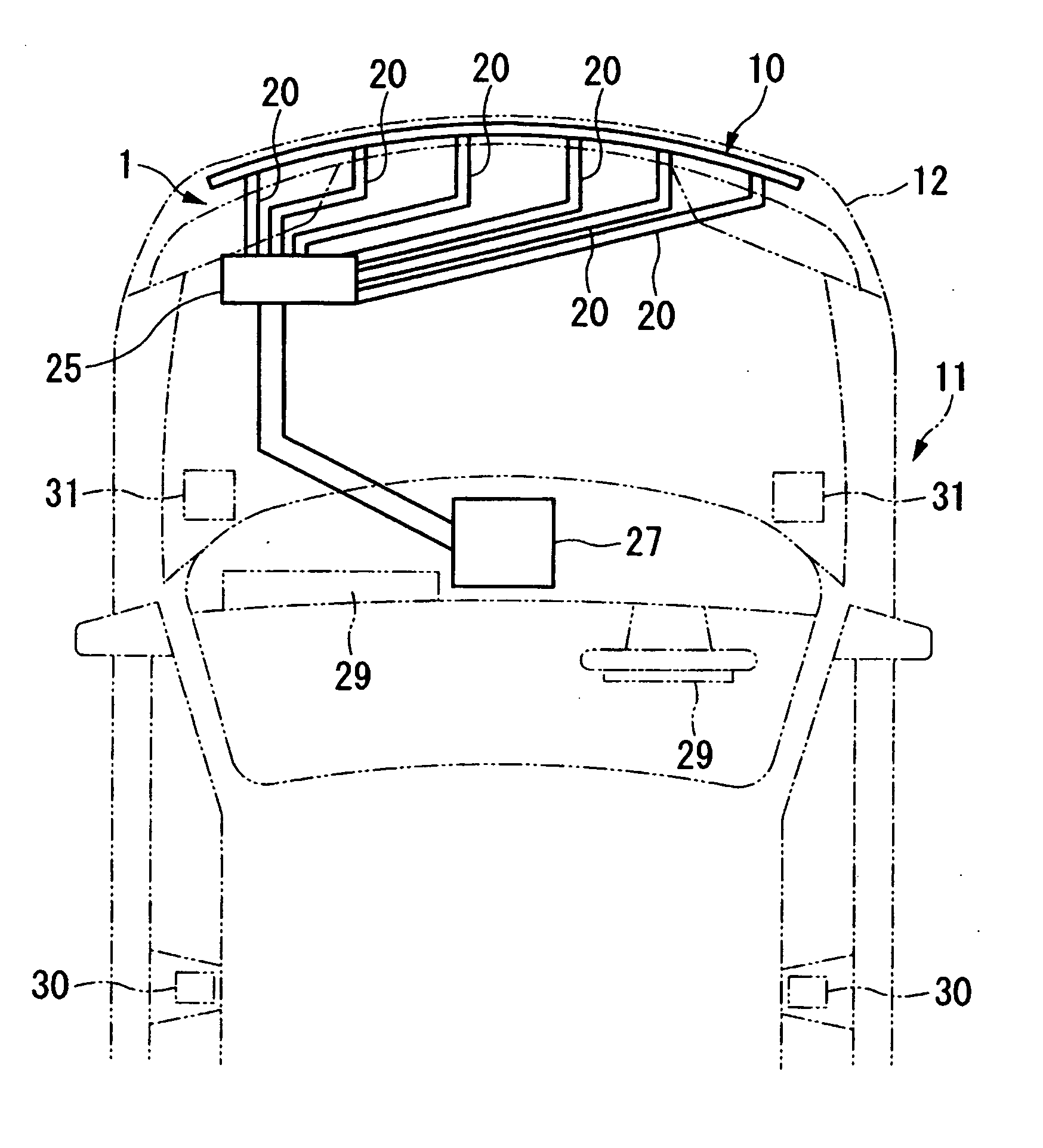
[0021] A first embodiment of a collision detection sensor for a vehicle and a collision detection device for a vehicle according to the present invention will be explained below with reference to the figures.

[0022] As shown in FIG. 1, a collision detection sensor for a vehicle (a collision detection sensor for a vehicle) 10 used in a collision detection device 1 for vehicles of the present embodiment is provided near the outer surface of a vehicle 11, and is used for detecting an input from the outside to vehicles 11, i.e., a collision. Specifically, the collision detection sensor for a vehicle 10 is provided on an inner surface of the front bumper face 12, and primarily detects a front collision.

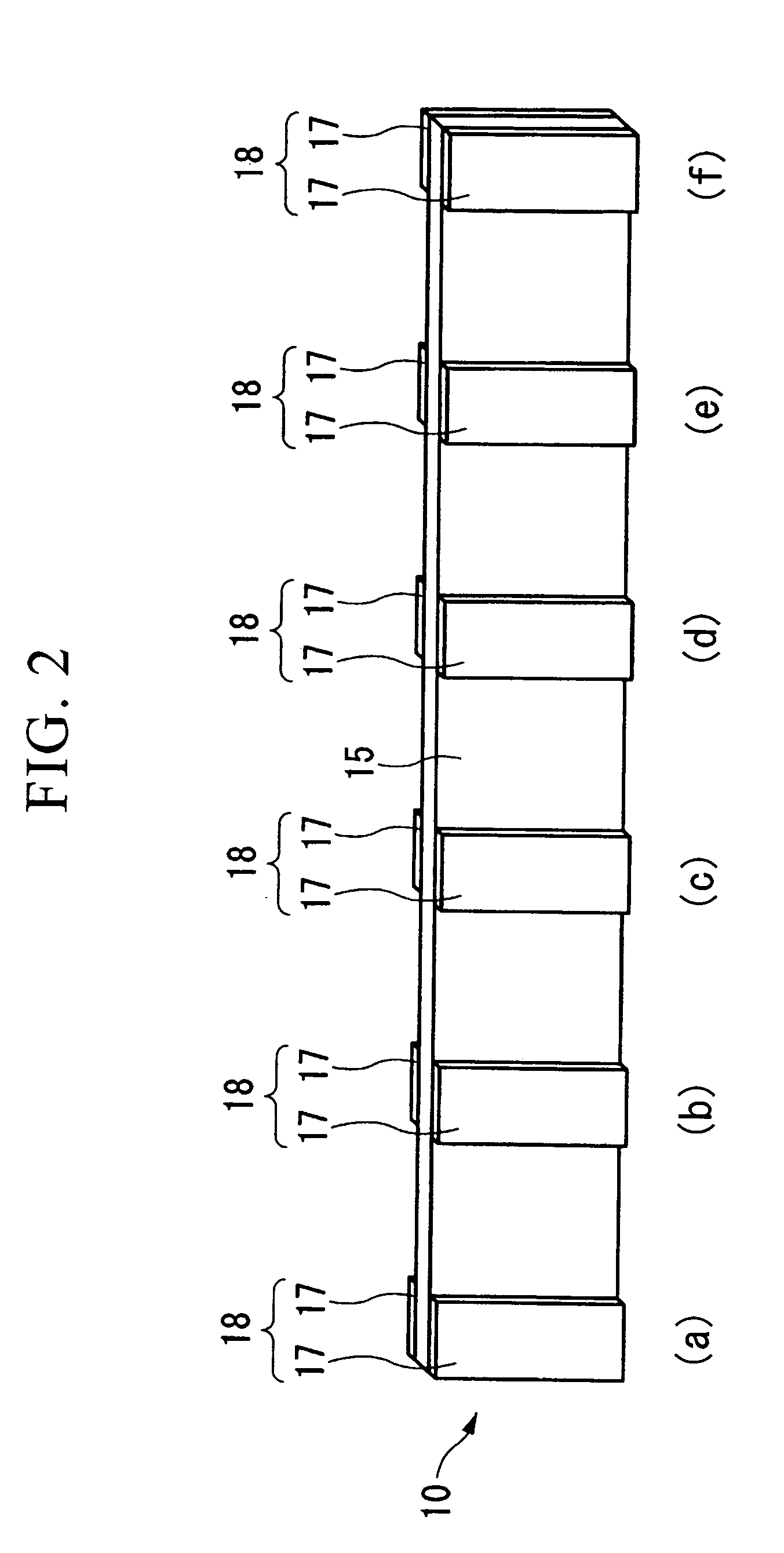
[0023] The collision detection sensor for a vehicle 10 is equipped with a piezoelectric film 15 which continuously extends along a plane as shown in FIG. 2. The piezoelectric film 15 is made of a macromolecular compound, and produces electrical charge when deformed, and conversely, deform...

second embodiment

[0039] A second embodiment of a collision detection sensor for a vehicle and a collision detection device for a vehicle according to the present invention will be explained below. Moreover, the same reference symbols will be applied to the same components explained in the above-mentioned first embodiment, and explanations thereof are omitted.

[0040] In a state in which a predetermined voltage is applied to one of the electrode units 18 on the piezoelectric film 15, the SRS control unit 27 of the present invention performs temperature compensation and failure judgment based on detected results by another electrode unit 18 which is different from the above-mentioned one electrode unit 18.

[0041] Specifically, the SRS control unit 27 uses one of the electrode units 18 as an electrode unit 18 for applying temperature compensation voltage, and applies a predetermined voltage to the electrode unit 18 for applying temperature compensation voltage, at a timing, for example, when an ignition...


PUM


Abstract

A collision detection sensor for a vehicle of the present invention includes a single piezoelectric film which is flat, plural pairs of electrodes which sandwich the piezoelectric film and measure voltages between the electrodes, and spaces provided between the plural pairs of electrodes.

Description

BACKGROUND OF THE INVENTION [0001] Priority is claimed on Japanese Patent Application No. 2003-389167, filed Nov. 19, 2003, and Japanese Patent Application No. 2003-389017, filed Nov. 19, 2003, the contents of which are incorporated herein by reference. [0002] 1. Field of the Invention [0003] The present invention relates to a collision detection sensor for vehicles and a collision detection device for vehicles which detect the collision of vehicles. [0004] 2. Description of Related Art [0005] As a technology concerning a collision detection sensor for a vehicle (or a collision detection device for a vehicle) which detects collision of vehicles, there is one having many sensor elements equipped with a piezoelectric film formed in the shape of a hexagon, and the sensor elements are so as to be flat by arranging them continuously (for example, refer to Published Japanese Translation No. H08-509934 of the PCT International Application). In such a collision detection sensor for a vehicl...

Claims


Application Information

Patent Timeline
IPC IPC(8): B60Q1/00B60R21/01B60R21/34G01P15/09
CPCB60R21/34B60R21/0136
Inventor MAE, HIROYUKIKAMEI, TAKAHIROTOBARU, SHIGEO
Owner HONDA MOTOR CO LTD
Why Eureka
Try Eureka