Bi-phase modulator for ultra wideband signals

a bi-phase modulator and ultra wideband technology, applied in the field of communication and radar systems, can solve the problems of large noise, large noise, and difficult to precisely manufacture, and achieve the effect of promoting excellent broadband phase and amplitude balance and reducing peak voltage swings

Inactive Publication Date: 2005-05-19
TIME DOMAIN
View PDF4 Cites 24 Cited by
  • Summary
  • Abstract
  • Description
  • Claims
  • Application Information

AI Technical Summary

Benefits of technology

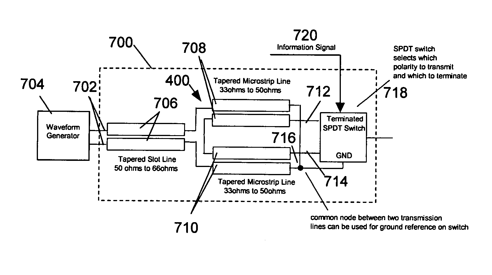
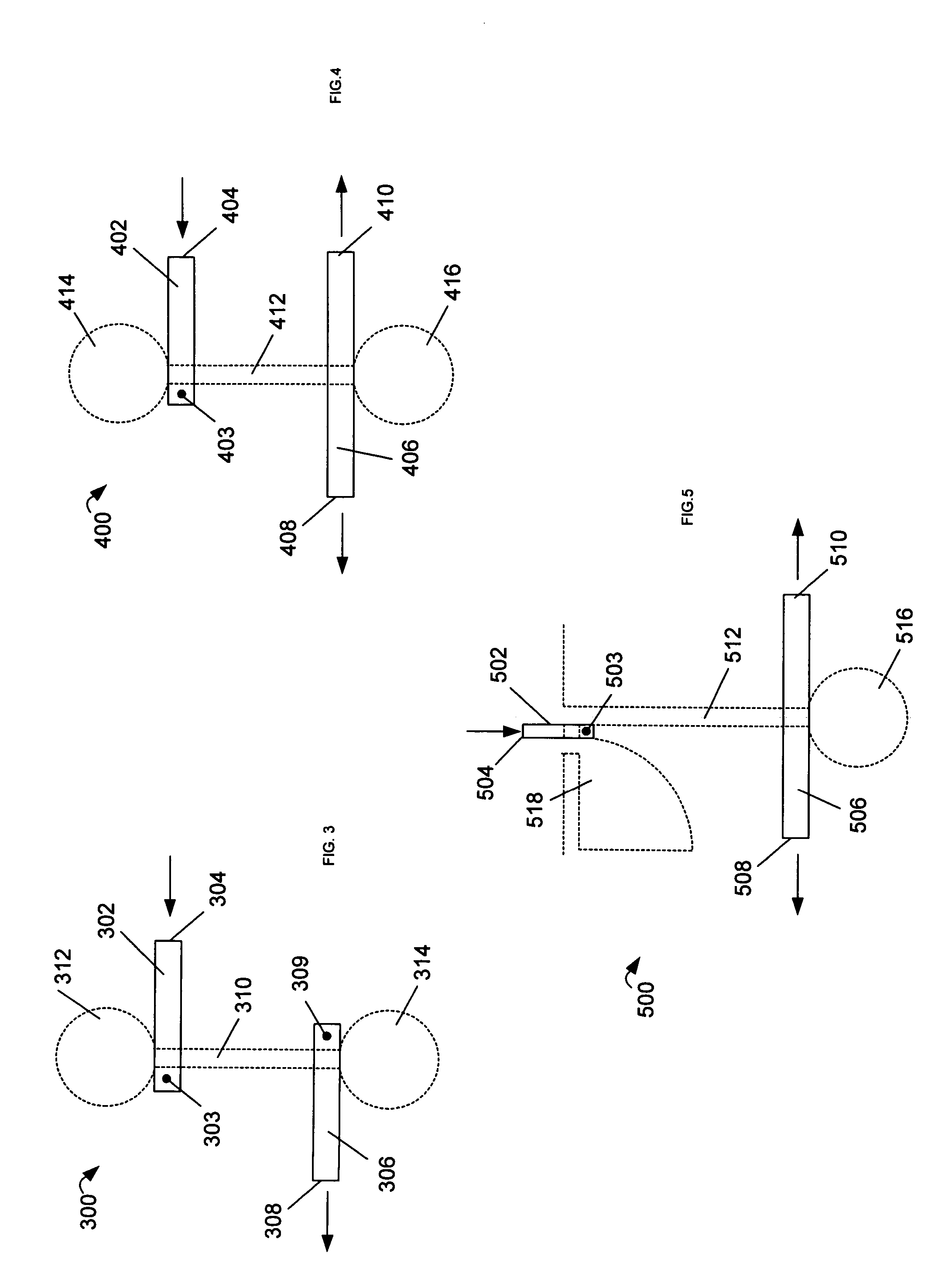
[0018] According to some of the more detailed features of the present invention, the electrically symmetrical structure of the symmetrical transformation device promotes excellent broadband phase and amplitude balance, and the absence of “stub” structures on the serially coupled input and output transmission lines substantially control phase delay dispersion across the bandwidth of the UWB signal. The transmission lines used in the present invention can be any one of several coupled line structures such as coaxial lines, slotlines, microstrips, and striplines, among others. The transmission lines are often tapered to provide impedance matching between the generator and load, or for other purposes such as reducing peak voltage swings on selecting (switching) devices in higher-power applications.

Problems solved by technology

The design and implementation of UWB systems and components requires the conveyance of these RF signals on unbalanced or balanced transmission lines.
One of the advantages of the balanced line is that an interfering magnetic field will not couple well to this structure, thus resulting in some noise immunity.
A problem arises when these wire / ferrite and printed line techniques are extended to higher frequencies (˜>1 GHz) where UWB signals are most often employed.
These structures of necessity become smaller and more difficult to precisely manufacture, and tend to develop excessive loss of signal, a loss in degree of balance, and electrical dispersion wherein different frequencies pass through the device with differing electrical delay.
However, distributed implementations can become increasingly problematic at lower frequencies (˜<1 GHz) because of the planar space they consume.
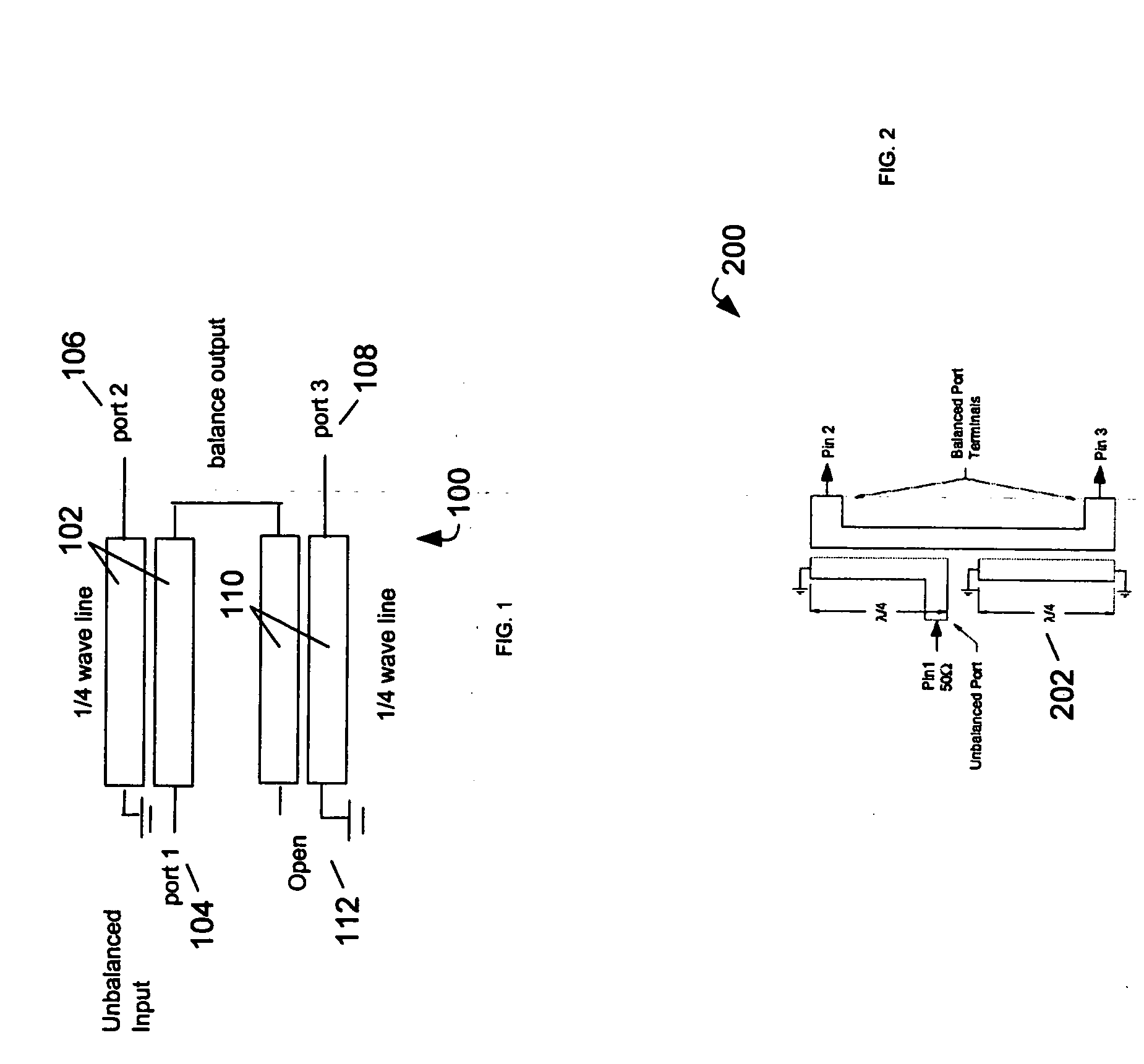
Stub transmission lines are known to introduce dispersion (phase delay) and this characteristic of the Marchand balun represents its primary failing for UWB.
Designs such as this, when based upon classic mixer structures utilized as a switchable crossover transformer, may suffer some of the maladies described earlier.
Because both of the wavelet generators must be turned on during data transmission, this form of UWB bi-phase generation suffers a power consumption penalty.
However, this approach suffers from the need for very careful matching of the timing performance of the two independent circuits.

Method used


Image

  • Bi-phase modulator for ultra wideband signals
  • Bi-phase modulator for ultra wideband signals
  • Bi-phase modulator for ultra wideband signals

Examples


Embodiment Construction

[0032] The bi-phase modulator of the present invention is used for modulating UWB signals in response to the state of an information signal. As herein defined, a UWB signal comprises any signal having relative bandwidth greater than or equal to 10% or defined as a UWB signal by communication rules and / or regulations of a governmental agency, for example, Federal Communications Commission (FCC) rules governing Part 15 signal emissions. UWB signals include, but are not limited to PPM, frequency, phase (e.g., flip) and amplitude modulated (or a combination thereof) signals that have an ultra-wide bandwidth. An information signal used for modulating the UWB signals according to the present invention comprises at least one of a data signal and a channelization signal. A data signal can correspond to binary data bits communicated over a communication channel. A channelization signal defines a communication channel, for example, a time hopping code. In one simple implementation, the bi-pha...


PUM


Abstract

A bi-phase modulator for Ultra Wideband (UWB) waveforms uses a symmetrical transformation device and a selector device to produce bi-phase modulated UWB waveforms in response to an information signal. The symmetrical transformation device receives an input UWB waveform and produces equal but opposite polarity output waveforms. The selector device determines whether an inverted or non-inverted UWB waveform is output in response to the information signal.

Description

FIELD OF THE INVENTION [0001] This invention relates to the fields of communication and radar systems and more particularly to bi-phase modulation of Ultra Wideband (UWB) signals. BACKGROUND OF THE INVENTION [0002] UWB technology holds great promise for a vast array of new applications that provide significant benefits for public safety, business, and consumers. These applications include, but are not limited to, the concurrent conveyance of voice, video, data, position information, and mono / bi-static radar detection. [0003] The FCC presently defines UWB as “An intentional radiator that, at any point in time, has a fractional bandwidth equal to or greater than 0.20 or has a UWB bandwidth equal to or greater than 500 MHz, regardless of the fractional bandwidth.”[Section 15.503] UWB technology is often referred to as “impulse radio” but may employ any of several types of transmitted waveforms. These bandwidths are often achieved by creating a short several-cycle waveform (a.k.a. pulse...

Claims


Application Information

Patent Timeline
Patent Type & Authority Applications(United States)
IPC IPC(8): H03K7/00H03K7/04
CPCH04B1/7174
Inventor FITZPATRICK, DOUGLAS DONTROUTMAN, DENNIS L.DICKSON, DAVID M.
Owner TIME DOMAIN
Why Eureka
Try Eureka