Method and apparatus for controlling a ventilator

a ventilator and control method technology, applied in the direction of valve operating means/release devices, process and machine control, instruments, etc., can solve the problems of not providing the automation of all factors, complicated adjustment, and particularly cumbersome adjustments in more fragile and less medically stable patients

Active Publication Date: 2005-05-26
TEHRANI FLEUR T
View PDF43 Cites 239 Cited by
  • Summary
  • Abstract
  • Description
  • Claims
  • Application Information

AI Technical Summary

Benefits of technology

[0012] A method and apparatus for controlling a ventilator includes first means receiving at least input data indicative of the patient's measured oxygen levels, and in a more elaborate embodiment of the invention, the first means also receives respiratory mechanics and / or pressure-volume data, as well as data indicative of measured carbon dioxide levels of the patient. The first means which preferably comprises a programmable microprocessor, is controlled by a software algorithm to operate on the input data, and to provide digital output data to control the ventilator and the gas mixer of the ventilator. The software algorithm is divided into two control programs. One control program which can either be used by itself or along with the other program, is designed to automatically adjust FIO2 and PEEP (or CPAP), based on at least the measured oxygen levels of the patient. The control program also operates on data from a pressure volume (PV) monitor / analyzer to set the initial PEEP value in certain groups of respiratory patients. The processing means detects hazardous conditions based on the input data and / or artifacts, replaces and / or corrects the measurement artifacts, and instructs generation of appropriate warning signals. The other control program, most of which is described in U.S. Pat. No. 4,986,268, is designed to control the frequency and ventilation for a next breath of the patient on the ventilator based on at least data indicative of measured CO2 and O2 levels of the patient, barometric pressure (as a reference pressure), and respiratory elastance and airway resistance (respiratory mechanics) data; and to make necessary adjustments in the I:E ratio based on the patient's respiratory mechanics data. The output data from the 1st means indicative of PEEP (or CPAP), FIO2, the adjustment in the I:E ratio, breathing frequency, and ventilation, and status of alarms are transmitted to a Signal Generator which is equipped with converters and / or other electronic components to generate the control and appropriate warning signals. The control signals for the breathing frequency, ventilation, PEEP (or CPAP), and the adjustment in the I:E ratio are supplied to the ventilator. The control signal for FIO2 is supplied to a mixer regulator unit which adjusts the concentration of oxygen added to the inhalation gas in the gas mixer of the ventilator. Based on the instructions from the 1st means, the alarm circuit generates appropriate warning signals when needed.

Problems solved by technology

However, despite much advancement in these devices, most ventilators used today are still mainly open-loop controlled devices and their added features have to some extent contributed to their complexity.
These adjustments are particularly cumbersome and frequent in more fragile and less medically stable patients.
The systems intended for controlling only the oxygen level of the patient on the ventilator, either do not provide the automation of all factors that affect oxygenation and / or they do not provide a reliable and sufficiently robust response against oxygen disturbances.

Method used


Image

  • Method and apparatus for controlling a ventilator
  • Method and apparatus for controlling a ventilator
  • Method and apparatus for controlling a ventilator

Examples


Embodiment Construction

Definitions

[0018] In the specification and claims:

[0019] 1—The term “ventilator” refers to a device which is used to provide total or assist ventilatory treatment to patients, and includes mechanical ventilators (i.e. artificial respirators) or CPAP (Continuous Positive Airway Pressure) machines.

[0020] 2—The term “PEEP” represents “Positive End-Expiratory Pressure” and is interchangeable with the term “CPAP,” which represents “Continuous Positive Airway Pressure,” for example, when assist ventilation is provided to spontaneously breathing subjects.

[0021] 3—The term “FIO2” represents “concentration of oxygen in a patient's inspiratory gas” which is the same as “fraction of inspired oxygen.”

[0022] 4—The term I:E represents the “ratio of inspiration time to expiration time.”

DESCRIPTION OF PREFERRED EMBODIMENTS

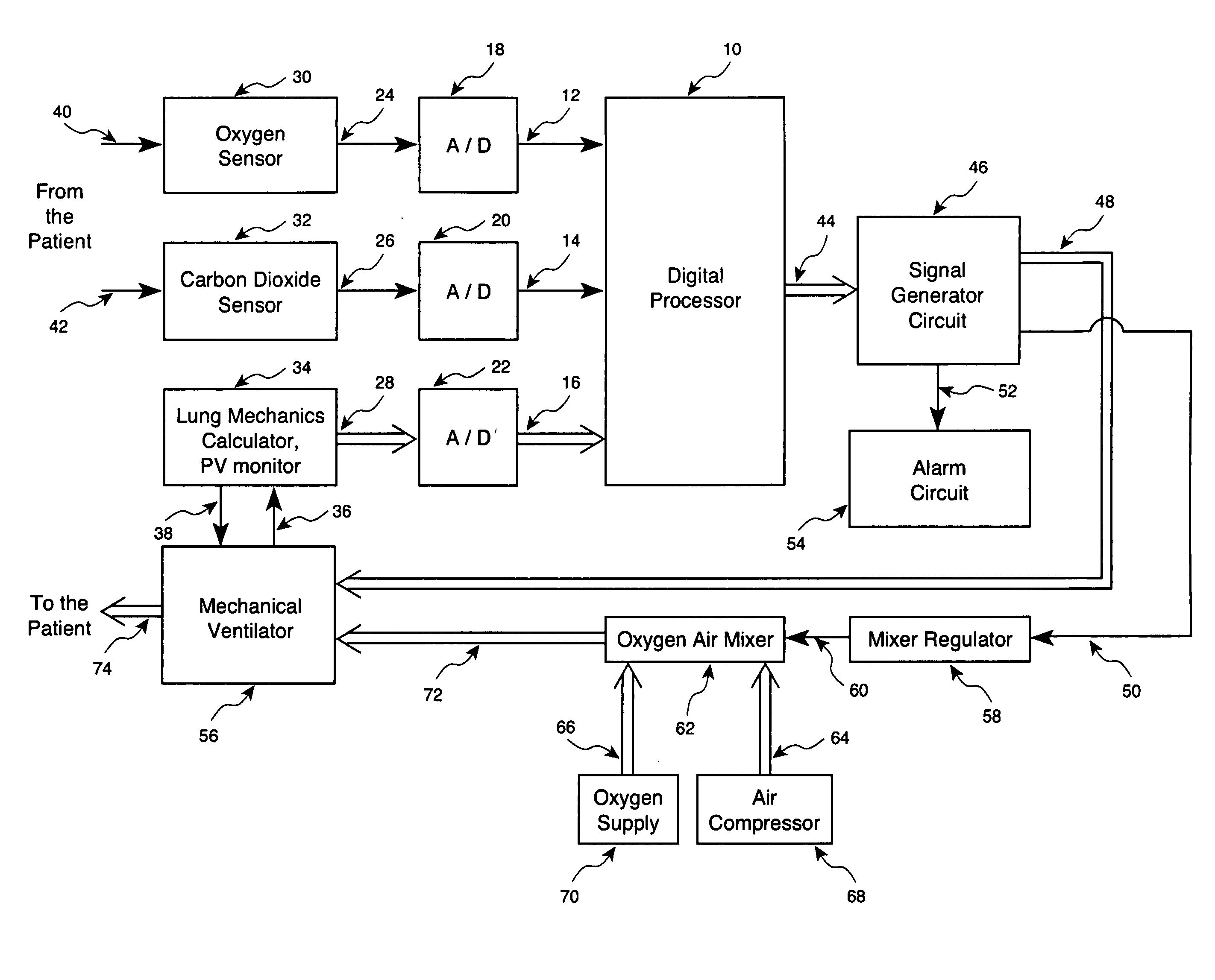
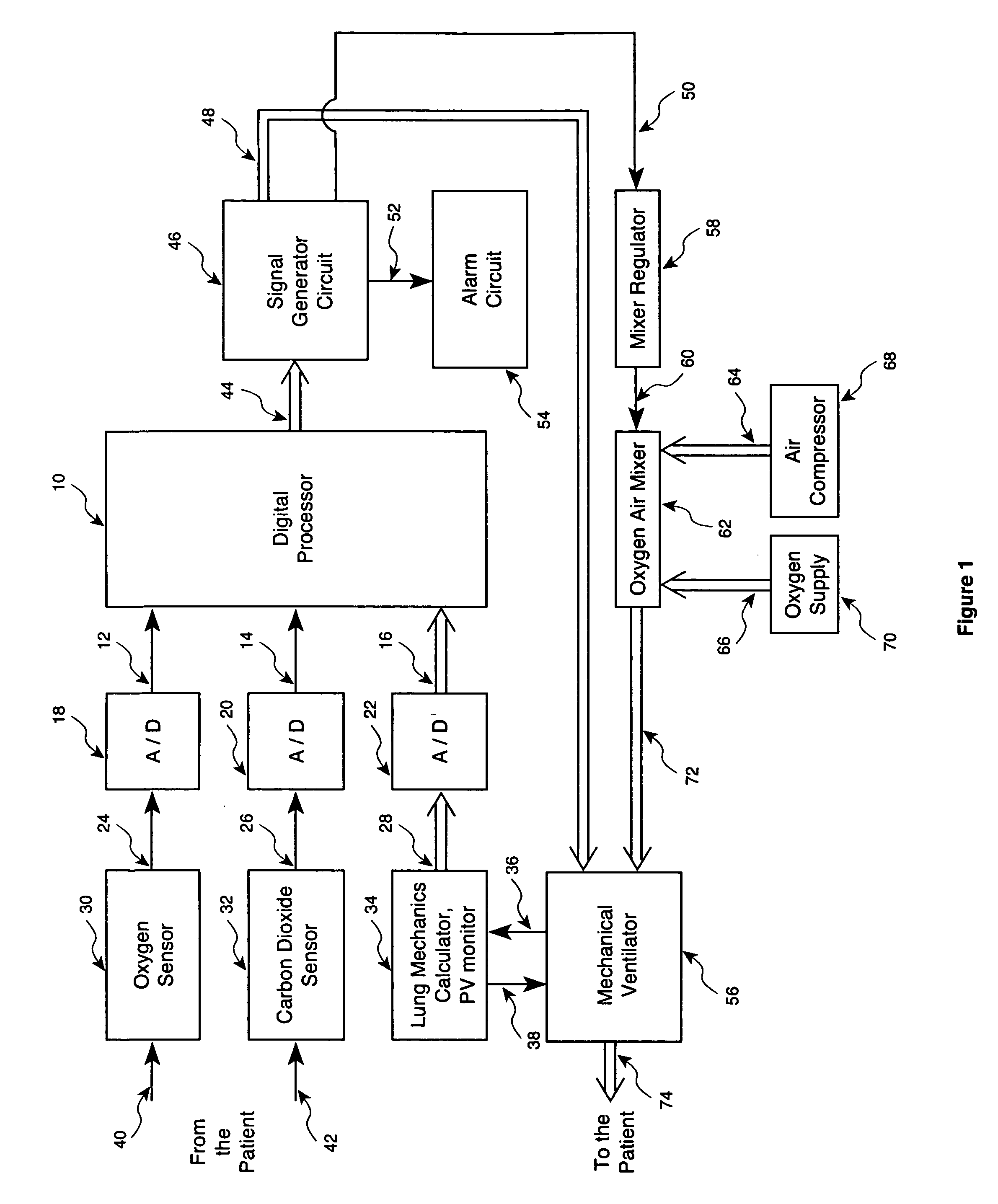
[0023]FIG. 1 shows a block diagram according to an alternative practice of the present invention. The digital processor 10 includes a programmable controller coupled to rece...


PUM


Abstract

Method and apparatus for controlling a ventilator are described. The invention can be used to control mechanical ventilators as well as respiratory assist devices such as CPAP machines. The apparatus receives input data indicative of patient's oxygen level. A controller determines PEEP, or CPAP, and FIO2, on the basis of data indicative of the patient's oxygen level. In an alternative embodiment, the apparatus further receives input data indicative of patient's carbon dioxide levels, respiratory elastance and airway resistance, and barometric pressure. The controller further utilizes the said input data to determine the optimal values of tidal volume and breathing frequency for a next breath of the patient, and uses the respiratory elastance and airway resistance data to determine any necessary adjustments in the I:E ratio. The controller also applies safety rules, detects and corrects artifacts, and generates warning signals when needed.

Description

CROSS REFERENCE TO RELATED APPLICATIONS [0001] This application claims the benefit of U.S. provisional patent application No. 60 / 481,693, filed Nov. 21, 2003, the entire contents of which are incorporated herein by reference. This application is related to U.S. Pat. No. 4,986,268 entitled “Method and Apparatus for Controlling an Artificial Respirator,” the disclosure of which is incorporated by reference.BACKGROUND OF INVENTION [0002] 1. Field of the Invention [0003] The present invention relates to a method and apparatus for controlling a ventilator such as a mechanical ventilator (i.e. an artificial respirator) or a respiratory assist device. In particular, the present invention relates to a method and apparatus for controlling a ventilator based on the measured levels of oxygen of the patient on the ventilator, as well as other physical conditions of the patient. [0004] 2. Background of the Invention [0005] Mechanical ventilators and other respiratory assist devices are extensive...

Claims


Application Information

Patent Timeline
Patent Type & Authority Applications(United States)
IPC IPC(8): A61M16/00
CPCA61M16/00A61M2202/0208A61M2230/435A61M2230/432A61M2230/205A61M16/0051A61M16/0063A61M16/026
Inventor TEHRANI, FLEUR T.
Owner TEHRANI FLEUR T
Why Eureka
Try Eureka