
Screwless faceplate components and assembly

Active Publication Date: 2005-05-26
PASS SEYMOUR
View PDF10 Cites 9 Cited by
  • Summary
  • Abstract
  • Description
  • Claims
  • Application Information

AI Technical Summary

Benefits of technology

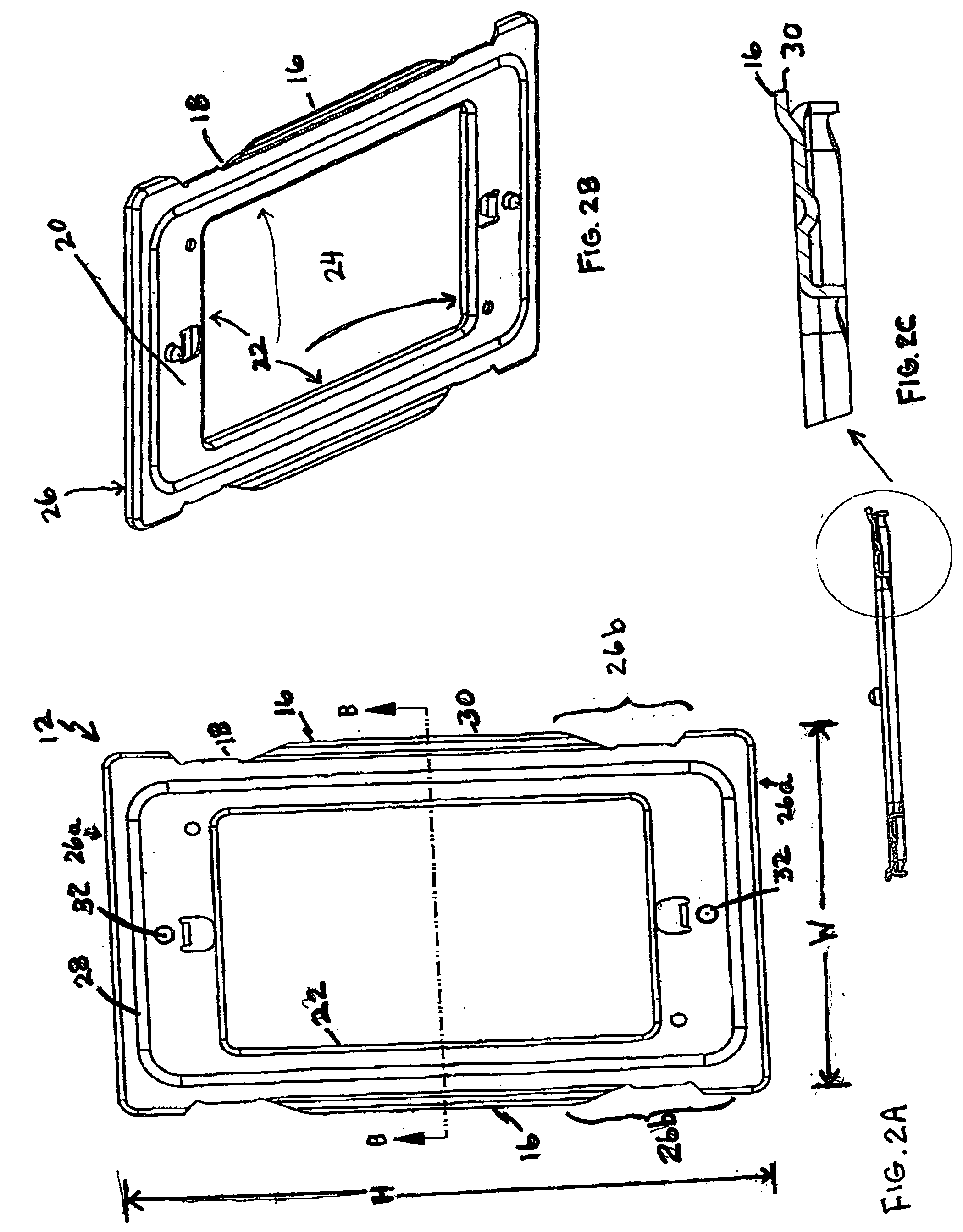
[0007] An embodiment of the invention is directed to a subplate component of a screwless faceplate assembly for use in conjunction with an electrical box. In an aspect of the embodiment, the subplate consists of a single monolithic subplate component in the form of a frame including a front surface and a back surface and having an outer perimeter defined by opposing outer horizontal surfaces and opposing outer vertical surfaces which include an integrated attachment structure, and an inner perimeter defined by smooth and continuous inner horizontal and vertical edges, said inner perimeter defining an uninterrupted subplate opening for accommodating one to N-gang electrical devices, where N is ≦8. In various aspects, the attachment structure forms at least part of the outer perimeter edge or is an integral portion of the outer perimeter surface. In a single gang aspect, the attachment structure is a lip extending along a portion of the outer vertical perimeter surfaces. In a multi-gang aspect, the attachment structure includes a lip extending along a portion of the outer vertical perimeter surfaces and an engagement assembly integrated into the outer horizontal perimeter edges. The engagement assembly may comprise two adjacent lips. All of the lips (alternatively, wings or catch-edges, and equivalent structures or edge-surface formations) are intended to be removeably engageable with complimentary attachment regions and structures in a faceplate component of a screwless faceplate assembly. Various aspects of the subplate component relate to the s

Problems solved by technology

The wall surface may be installed in ill-measured pieces that may not provide an even or smooth finished surface.
Moreover, the wall surface may have a textured finish, or a fabric finish, that may not be even or firm.
The segmented construction of the coupling plate, along with the observation that the coupling plate is likely of a plastic or similar semi-rigid material, may not provide the desired rigidity that upon installation will smoothly cover an uneven, soft, or defective wall surface.
On the other hand, in remodeling work it is not always practical to remove large sections of existing wall surface merely to mount electrical boxes and run cable.

Method used


Image

  • Screwless faceplate components and assembly
  • Screwless faceplate components and assembly
  • Screwless faceplate components and assembly

Examples


Embodiment Construction

[0031] As described and claimed herein, embodiments of the invention relate, respectively, to a subplate component, a faceplate component, and a screwless faceplate assembly consisting of a subplate component and a faceplate component. Throughout the following detailed description, mixed references will be made to the individual components and the assembly consisting of the components to give the reader a comprehensive understanding of the various embodiments.

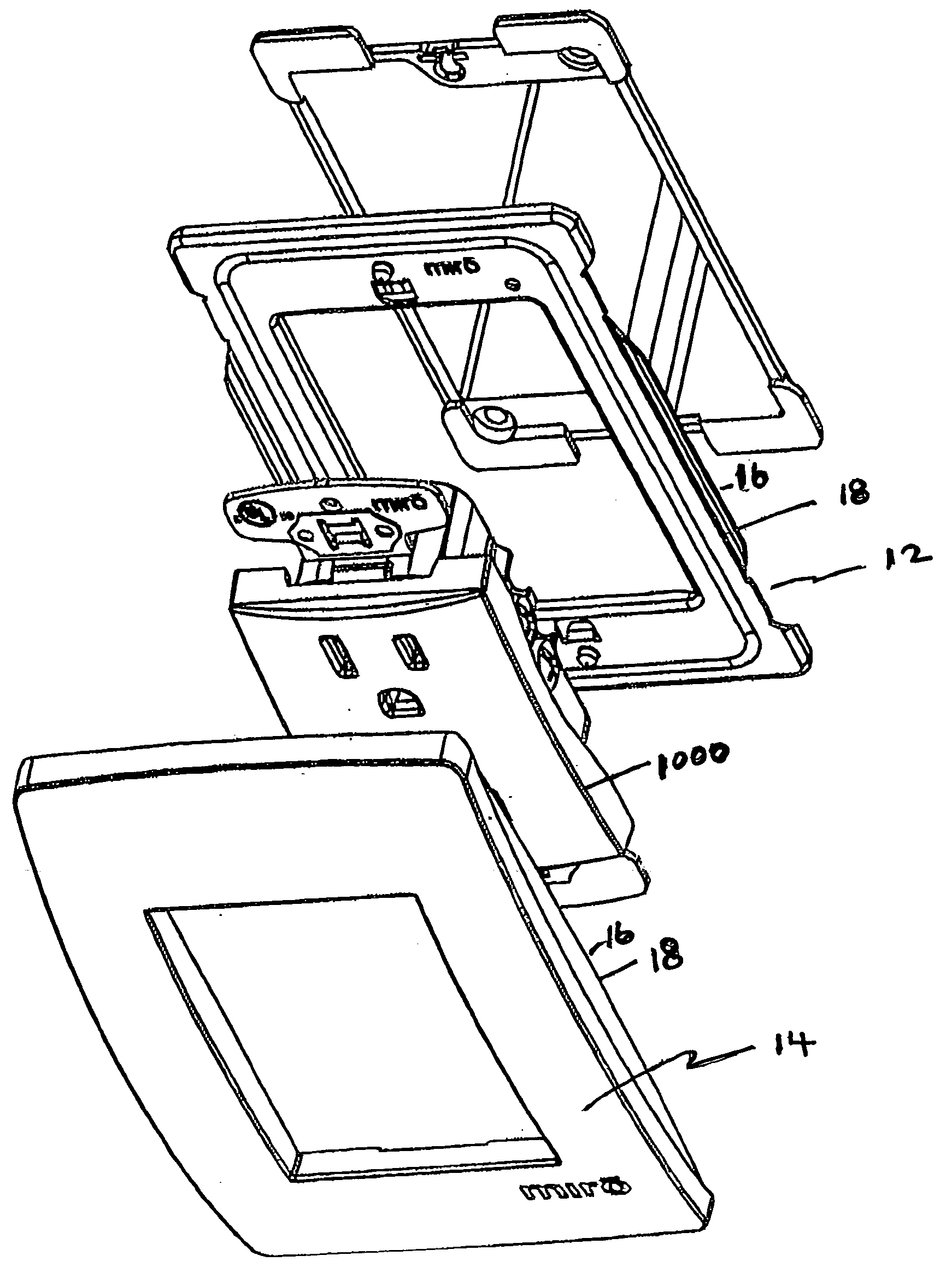
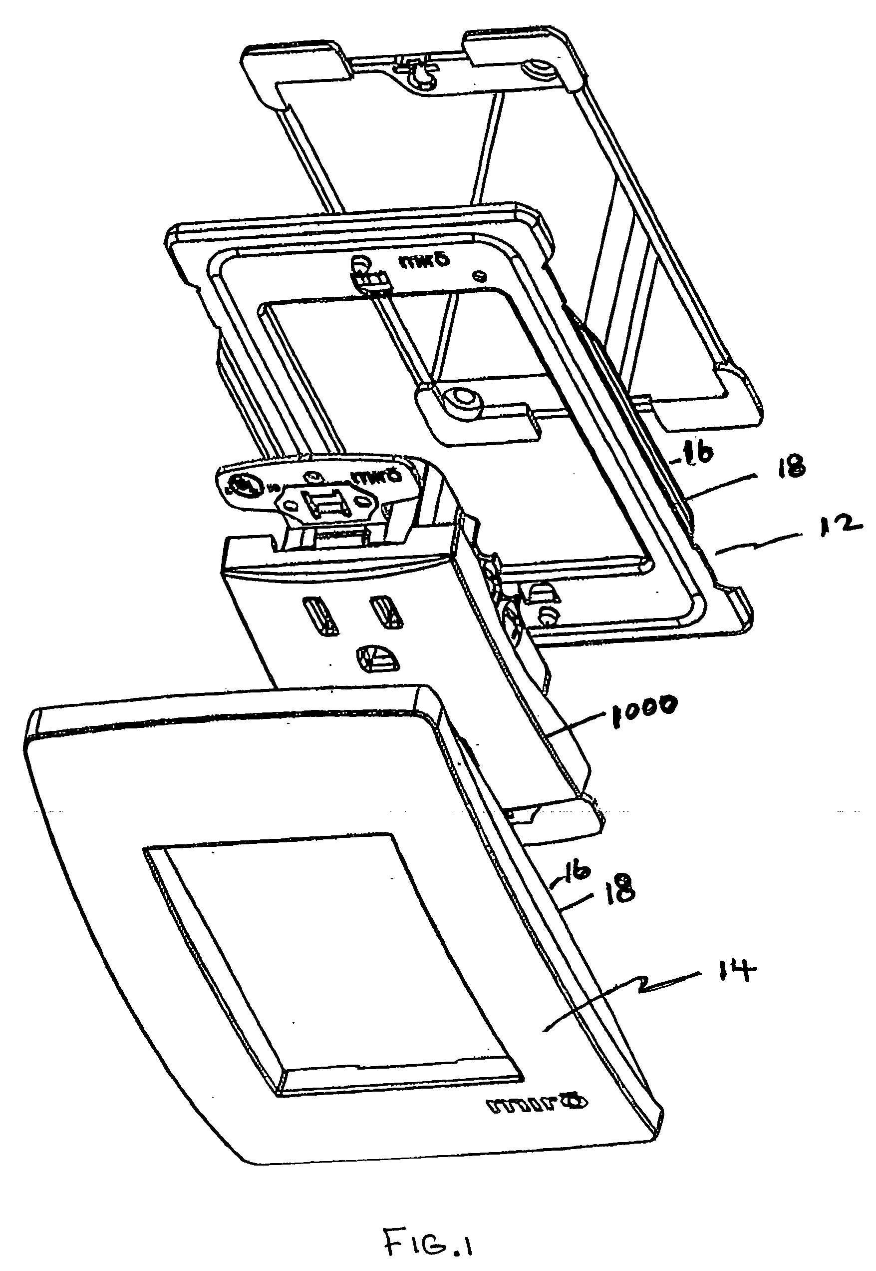
[0032] Exploded views of exemplary aspects of a screwless faceplate assembly 10 are illustrated in FIGS. 1, 5A, 8 and 10. The faceplate assembly 10 consists of a subplate component 12 and a faceplate component 14 that is removably attachable to the subplate without the use of screw fasteners or other external attachment means. The subplate component and the faceplate component have respective, integral, complimentary, reversible co-engagement means only located on, or immediately adjacent, outer perimeter surfaces thereof as i...


PUM


Abstract

A screwless faceplate assembly consisting of a single monolithic subplate component and a single monolithic faceplate component that is removeably attachable to the subplate component. Both the subplate component and the faceplate component have complimentary, respective, reversible co-engagement means only located adjacent outer perimeter surfaces thereof. The subplate component is metallized or otherwise reinforced such that upon installation against an existing, potentially non-flat or uneven wall surface, the proper position and spacing of multiple electrical devices engaged with the subplate component are maintained. Embodiments of the invention include a subplate component and a faceplate component, and, upon assembly, a screwless faceplate assembly.

Description

BACKGROUND OF THE INVENTION [0001] 1. Field of the Invention [0002] Embodiments of the invention are generally directed to the field of electrical wiring components, and more particularly to a screwless faceplate assembly and the components thereof, for use in conjunction with an electrical receptacle box or the like. [0003] 2. Description of Related Art [0004] Conventional electrical box cover plates, referred to herein as faceplates, are typically constructed in the form of a flat plastic or metallized plate having one or more openings that provide access to a wired device mounted in the electrical box. The purpose of the faceplate is to provide a decorative cover for the electrical box installation while also preventing operator exposure to the interior of the electrical box, which contains electrical wiring. As used herein, “wired device” refers generally to any of a variety of electrical power control / distribution devices including, but not limited to, ON / OFF switches, outlet r...

Claims


Application Information

Patent Timeline
IPC IPC(8): H02G3/14
CPCH02G3/14
Inventor ROHMER, RICHARD
Owner PASS SEYMOUR
Learn More