
System, chamber, and method for fractionation and elutriation of fluids containing particulate components

Inactive Publication Date: 2006-04-27
CRYOFACETAB
View PDF16 Cites 26 Cited by
  • Summary
  • Abstract
  • Description
  • Claims
  • Application Information

AI Technical Summary

Benefits of technology

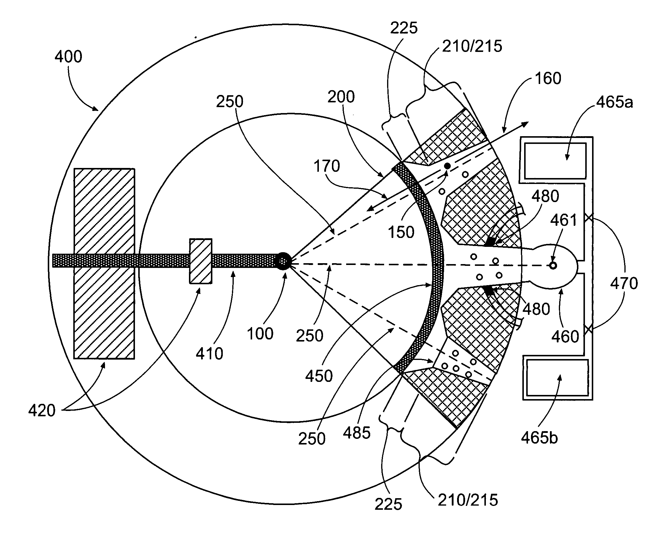
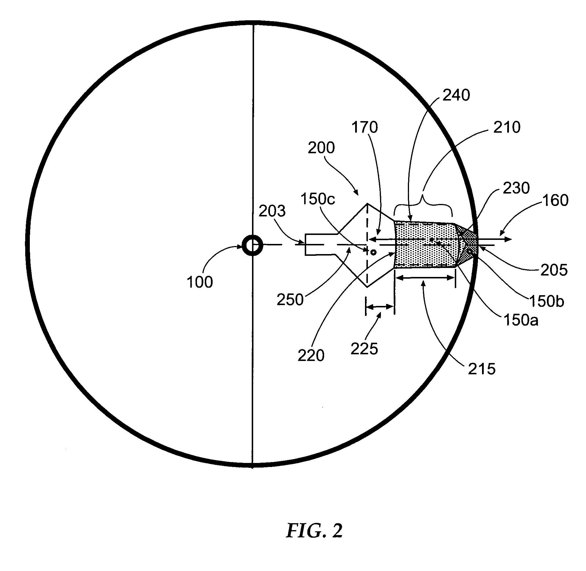
[0011] According to some aspects of the present invention, the system and chamber may further define a radially-extending duct wherein the duct further comprises an upper wall extending radially outward from the central axis of the centrifuge and a lower wall extending radially outward from the central axis of the centrifuge. Furthermore, the upper wall and the lower wall may be formed so as to converge about a plane of rotation defined by a radius extending radially outward from the central axis by such that the duct cross-sectional area is configured to decrease in relation to the radial distance from the central axis. Furthermore, in some embodiments having convergent upper and lower walls, the duct may extend radially outward 360 degrees about the central axis while still defining a duct cross-sectional area that decreases in relation to a radial distance from the central axis. Thus, the 360 degree duct may not only provide for a greater overall duct volume, and eliminate the need for side walls, but the 360 degree duct may still provide a duct geometry configured such that the centrifugal force exerted on the at least one component by the chamber rotating about the central axis of the centrifuge device substantially opposes a drag force exerted on the at least one component by the fluid along the length of the duct.
[0016] Embodiments of the present invention may advantageously provide a system, chamber, and method whereby the at least one component separated from the fluid is spread uniformly through the radial length of the duct. Thus, instead of providing a radially-narrow packed equilibrium zone, as is common in conventional elutriation chambers, the embodiments of the chamber and system of the present invention provide a duct wherein the components are spaced far apart radially within the duct. Thus, according to advantageous aspects of the present invention, components of different sizes may pass readily through the duct so as to provide increased separation of the at least one component from the fluid and / or other components suspended in the fluid. In addition, the liquid in which the at least one component is initially disposed may be displaced easily by a supply of elutriation fluid so as to enable more thorough washing of the at least one component.

Problems solved by technology

When transfused to a recipient, leukocytes do not benefit the recipient.
In fact, foreign leukocytes in transfused red blood cells and platelets are often not well tolerated and have been associated with some types of transfusion complications.
Some of these species, as well as ozone itself, can damage blood and other cells.
Specifically, excessively oxidizing environments, such as those associated with ozone, damage red blood cells.
These radicals are so energetic that they may “burn” any proteins they encounter.
The immediate degradation products are proteins that are so severely damaged that they cannot function, as well as lower energy ROS that proceed to cause even more protein damage.
Finally, ROS formation within the cell itself will result in destruction of all of the local cell contents.
In addition, conventional centrifugal elutriation techniques provide for nominal fractionation of blood components (such as red blood cells, white blood cells, platelets, etc.), however, such conventional techniques often lack the capability of effectively washing out, via centrifugation, plasma and / or O2 so as to allow for the safe and effective addition of other decontaminating agents and or energy (such as ozone and / or UVC energy) without the generation of Heinz bodies or other harmful effects in the remaining blood components.
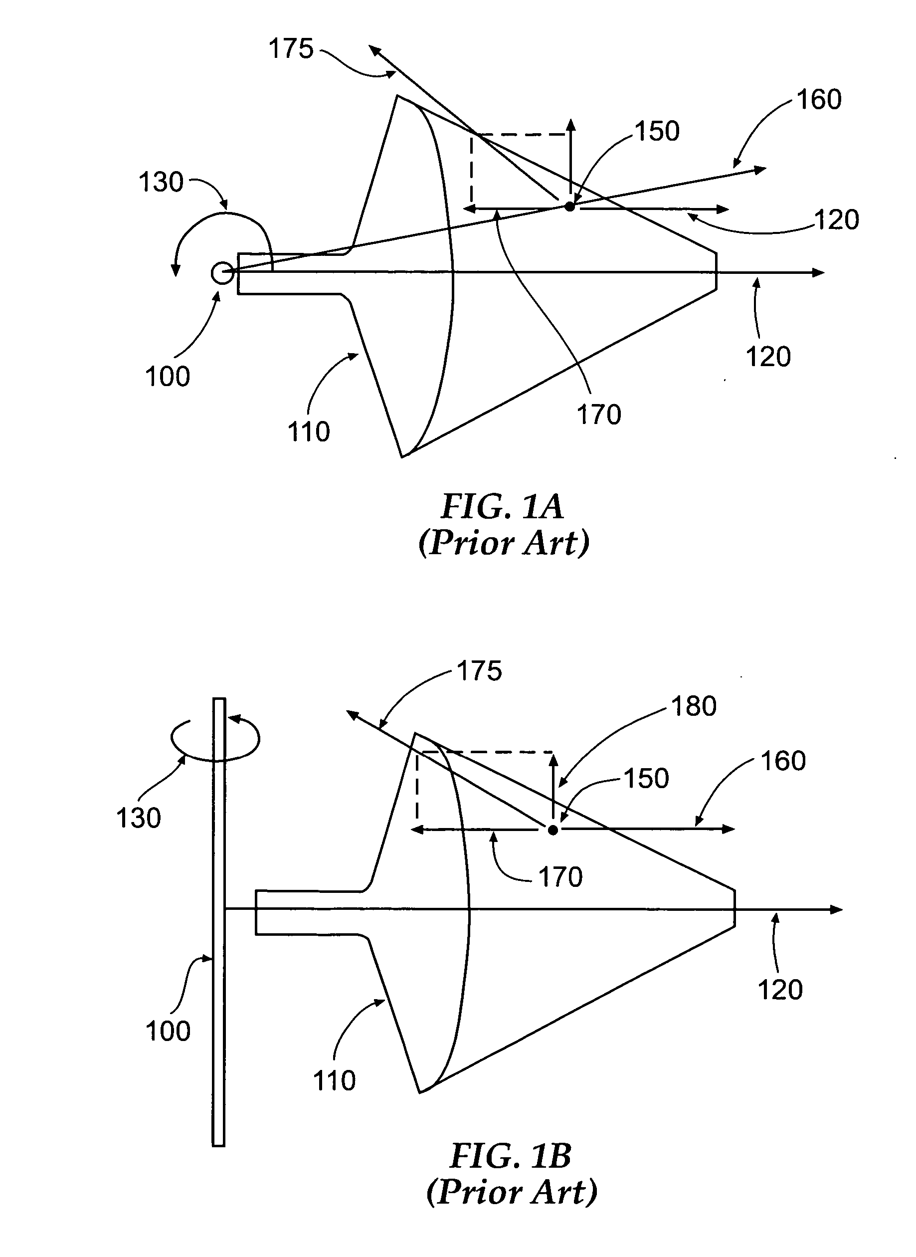
However, in conventional elutriation chambers (which, in most cases, define a sharply decreasing cross-sectional area moving radially outward from the centrifuge shaft (i.e., a “cone” shape) (as shown generally in FIG. 1, herein)) the various cell components may be tightly packed within their respective equilibrium layers such that some components may be unable to reach their respective equilibrium layer through an adjacent layer of densely packed cells.
As a result, it is difficult for cells of different sizes to cross opposing equilibrium layers, even if their respective density and / or size values would predictably cause these components to be separated by centrifugal force.
In particular, cells of similar size (but having different mass / density) are often difficult to separate due to both close-packing and aggregation of cells (particularly for red blood cells which are similar in size to some leukocytes, but have much greater density values per unit size, on average).
In addition, the close-packing induced by conventional elutriation chambers also impedes washing techniques as well as pathogen inactivation processes, in which all cell surfaces must be readily accessible in order to more effectively decontaminate and / or fractionate a blood sample.
For instance, in conventional elutriation chambers, cells are close-packed within their relative equilibrium layers such that plasma components may not be adequately washed out of the blood unit by elutriating fluid that may be pumped into the elutriation chamber from the radially outward direction, thus precluding the safe use of ozone decontamination for the remaining blood components.

Method used


Image

  • System, chamber, and method for fractionation and elutriation of fluids containing particulate components
  • System, chamber, and method for fractionation and elutriation of fluids containing particulate components
  • System, chamber, and method for fractionation and elutriation of fluids containing particulate components

Examples


Embodiment Construction

[0030] The present inventions now will be described more fully hereinafter with reference to the accompanying drawings, in which some, but not all embodiments of the invention are shown. Indeed, these inventions may be embodied in many different forms and should not be construed as limited to the embodiments set forth herein; rather, these embodiments are provided so that this disclosure will satisfy applicable legal requirements. Like numbers refer to like elements throughout.

[0031] While the embodiments of the system, chamber, and method for elutriating biological fluids containing particulate components including, for instance, whole blood, are described below in the context of the fractionation and washing of whole blood components including plasma, platelets, red blood cells (erythrocytes), white blood cells (leukocytes), platelets (thrombocytes) and other blood components, it should be understood that the embodiments of the present invention may also be utilized to fractionat...


PUM

PropertyMeasurementUnit
Lengthaaaaaaaaaa
Lengthaaaaaaaaaa
Lengthaaaaaaaaaa

Abstract

A chamber, system, and method for separating a selected component from a fluid are provided. The chamber is capable of rotating about the central axis of a centrifuge device and includes a radially-extending duct having an optimized variable cross-sectional area that decreases in relation to the outward radial distance from the central axis of the centrifuge. The optimized geometrical design of the duct provides that a centrifugal force exerted on the selected component caused by the rotation of the chamber substantially balances the drag force exerted on the selected component by the fluid as the selected component flows through the duct. Thus, the duct allows the selected component to be dispersed in equilibrium along the radial length of the duct such that the selected component may be effectively suspended with the duct and / or separated from the fluid using elutriation or other methods.

Description

CROSS-REFERENCE TO RELATED APPLICATION [0001] This application claims the benefit of U.S. Provisional Application No. 60 / 621,174, filed Oct. 22, 2004, which is incorporated by reference herein in its entirety.FIELD OF THE INVENTION [0002] The present invention relates generally to the separation and / or purification of particulate and / or cellular components of a biological fluid, such as blood, by a centrifugation process such that the components may be effectively and safely decontaminated and separated for a variety of downstream uses, including transfusion, research, and other uses. Specifically, the present invention provides a chamber and duct for elutriation having an optimized geometry for distributing a specific component within a radially-extending duct so as to more effectively separate and / or wash the specific component during a centrifugation and / or elutriation process. BACKGROUND OF THE INVENTION [0003] Biological fluids, such as whole blood, may include a complex mixtur...

Claims


Application Information

Patent Timeline
IPC IPC(8): B01D21/26
CPCA61M1/3693B04B5/0442B04B2005/0471A01N1/0236B01D2221/10B04B2005/0478A61M1/3696B01D21/262A61M1/3692
Inventor E. PURDUM, HOWARD
Owner CRYOFACETAB
Learn More