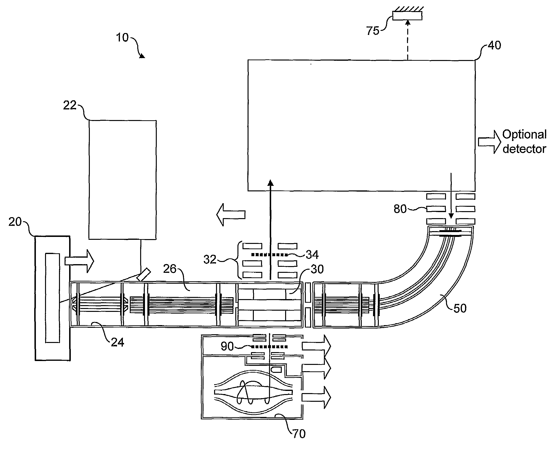
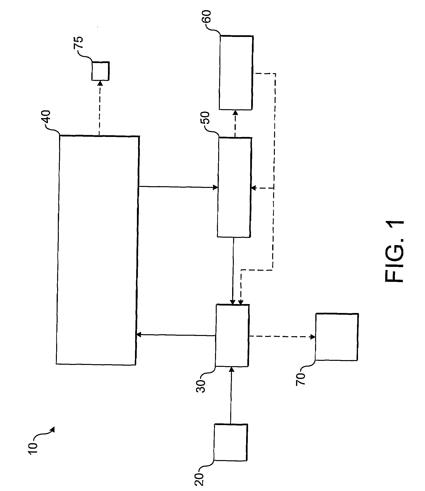
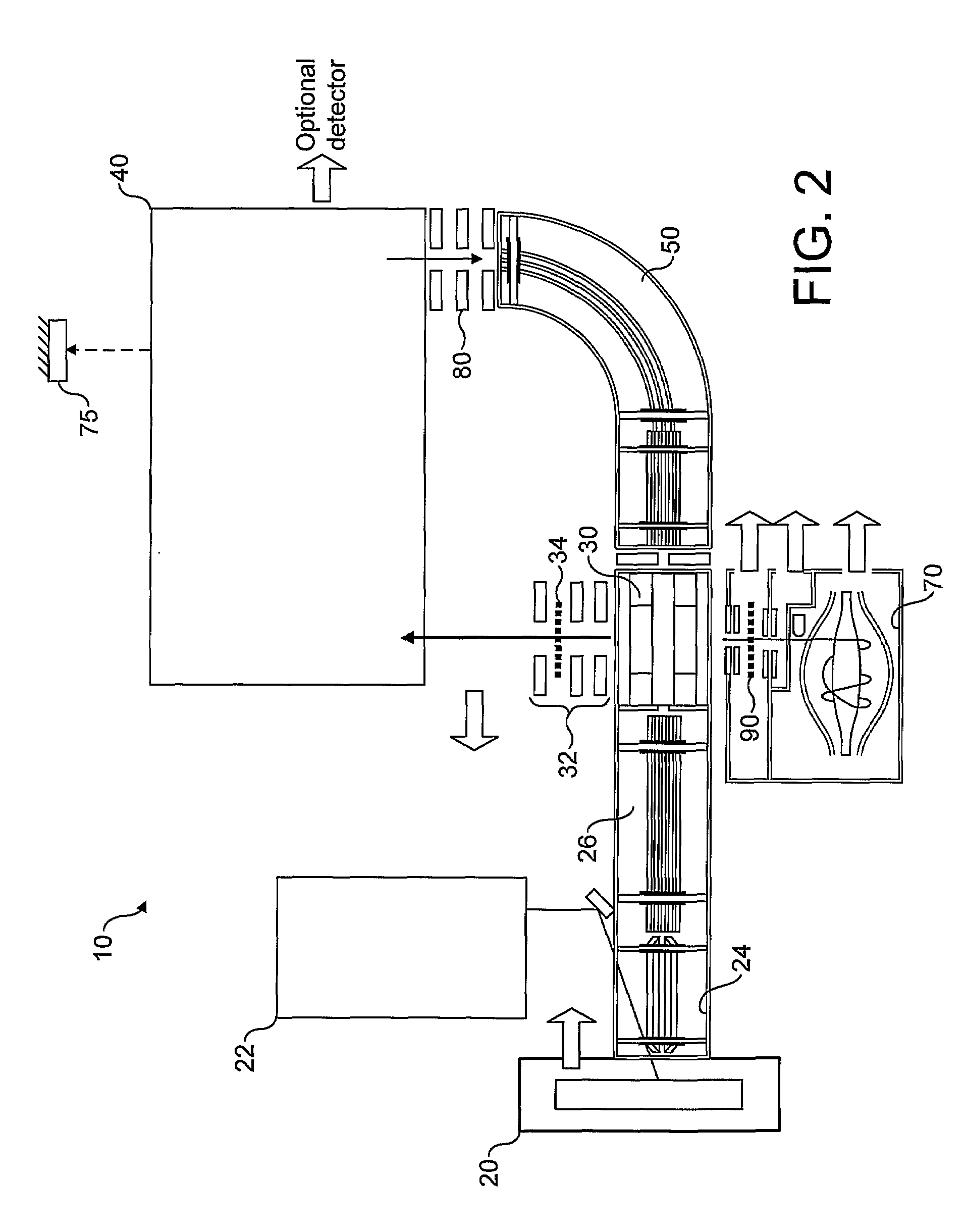
[0009]The present invention thus employs a cyclical arrangement in which ions are trapped, optionally cooled, and ejected from an exit aperture. A subset of these ions are returned to the ion storage device. This cyclical arrangement provides a number of advantages over the art identified in the introduction above, which instead employs a “back and forth” procedure via the same aperture in the
ion trap. Firstly, the number of devices required to store and inject ions into the ion selector is minimised (and in the preferred embodiment is just one). Modern storage and injection devices that permit very high mass resolution and
dynamic range are expensive to produce and demanding to control so that the arrangement of the present invention represents a significant cost and control saving over the art. Secondly, by using the same (first) ion storage device to inject into, and receive ions back from, an external ion selection device, the number of MS stages is reduced. This in turn improves ion transport efficiency which depends upon the number of MS stages. Typically, ions ejected from an external ion selector will have very different characteristics to those of the ions ejected from the ion storage device. By loading ions into the ion storage device through a dedicated ion inlet port (a first ion transport aperture), particularly when arriving back at the ion storage device from an external fragmentation device, this process can be carried out in a well controlled manner. This minimises ion losses which in turn improves the ion transport efficiency of the apparatus.
[0011]Optionally, at the same time as the low abundance precursor ions are being moved to the second ion storage device to improve
total population of these particular precursor ions, the ion selection device may continue to retain and further refine the selection of other desired precursor ions. When sufficiently narrowly selected, these precursor ions can be ejected from the ion selection device and fragmented in a fragmentation device to produce fragment ions. These fragment ions may then be transferred to the first ion storage device, and MSn of these fragment ions may then be carried out or they may likewise be stored in the second ion storage device so that subsequent cycles may further enrich the number of ions stored in this way to again increase the
detection limit of the instrument for that particular fragment ion.
[0015]An
ion source may be provided to supply a continuous or pulsed
stream of sample ions to the ion storage device. In one preferred arrangement, the optional fragmentation device may be located between such an
ion source and the ion storage device instead. In either case, complicated MSn experiments may be carried out in parallel by allowing division of (and, optionally,
separate analysis of)
sub populations of ions, either directly from the
ion source or deriving from previous cycles of MS. This in turn results in an increase in the
duty cycle of the instrument and can likewise improve the detection limits of it as well.
[0022]Any form of electrostatic trap may be used, if this is what constitutes the ion selection device. A particularly preferred arrangement involves an EST in which the
ion beam cross-section remains limited due to the focusing effect of the electrodes of the EST, as this improves efficiency of the subsequent ion ejection from the EST. Either an open or a closed type EST could be used. Multiple reflections allow for increasing separation between ions of different mass-to-charge ratios, so that a
specific mass-to-charge ratio of interest may, optionally, be selected, or simply a narrower range of mass-to-charge ratios than was injected into the ion selection device. Selection could be done by deflecting unwanted ions using electric pulses applied to dedicated electrodes, preferably located in the plane of time-of-flight focus of ion mirrors. In the case of closed EST, a multitude of deflection pulses might be required to provide progressively narrowing m / z ranges of selection.
[0023]It is possible to use the fragmentation device in two
modes: in a first mode, precursor ions can be fragmented in the fragmentation device in the usual manner, and in a second mode, by controlling the
ion energy, precursor ions can pass through the fragmentation device without fragmentation. This allows both MSn and ion abundance improvement, together or separately: once ions have been injected from the first ion storage device into the ion selection device, specific low abundance precursor ions can be ejected controllably from the ion selection device and be stored back in the first ion storage device, without having been fragmented in the fragmentation device. This may be achieved by passing these low abundance precursor ions through the fragmentation device at energies insufficient to cause fragmentation. Energy spread could be reduced for a given m / z by employing pulsed deceleration fields (e.g. formed in a gap between two flat electrodes with apertures). When ions enter a decelerating
electric field on the way back from the mass selector to the first ion storage device, higher energy ions overtake lower energy ions and thus move to a greater depth in the deceleration field. After all the ions of this particular m / z enter the deceleration field, the field is switched off. Therefore ions with initially higher energy experience a higher drop in potential relatively to ground potential than the lower energy ions, thus making their energies equal. By matching the potential drop to the energy spread upon exit from the mass selector, a significant reduction of the energy spread may be achieved. Fragmentation of ions may thereby be avoided, or, alternatively, control over the fragmentation may be improved.


