Apparatus and method for cleaning membrane filtration modules
What is AI technical title?
AI technical title is built by PatSnap AI team. It summarizes the technical point description of the patent document.
a technology of filtration module and apparatus, which is applied in the direction of filtration separation, membranes, separation processes, etc., can solve the problems of large energy consumption, inability to achieve continuous filtering, so as to improve the quality of filtrate and reduce the residence time
Inactive Publication Date: 2005-05-26
SIEMENS IND INC
View PDF99 Cites 56 Cited by
Summary
Abstract
Description
Claims
Application Information
AI Technical Summary
This helps you quickly interpret patents by identifying the three key elements:
Problems solved by technology
Method used
Benefits of technology
Benefits of technology
[0010] Preferably, the gas bubbles are entrained into said liquid stream by means of a venturi device. For further preference, the gas bubbles are entrained or injected into said liquid stream by means of devices which forcibly mix gas into a liquid flow to produce a mixture of liquid and bubbles, such devices including a jet, nozzle, ejector, eductor, injector or the like. Optionally, an additional source of bubbles may be provided in said liquid medium by means of a blower or like device. The gas used may include air, oxygen, gaseous chlorine or ozone. Air is the most economical for the purposes of scrubbing and / or aeration. Gaseous chlorine may be used for scrubbing, disinfection and enhancing the cleaning efficiency by chemical reaction at the membrane surface. The use of ozone besides the similar effects mentioned for gaseous chlorine, has additional features, such as oxidising DBP precursors and converting non-biodegradable NOM's to biodegradable dissolved organic carbon.
[0017] The fibre bundle is protected and fibre movement is limited by a module support screen which has both vertical and horizontal elements appropriately spaced to provide unrestricted fluid and gas flow through the fibres and to restrict the amplitude of fibre motion reducing energy concentration at the potted ends of the fibres.
[0025] If required, a further source of aeration may be provided within the tank to assist microorganism activity. For preference, the membrane module is suspended vertically within the tank and said further source of aeration may be provided beneath the suspended module. Preferably, the further source of aeration comprises a group of air permeable tubes. The membrane module may-be operated with or without backwash depending on the flux. A high mixed liquor of suspended solids (5,000 to 20,000 ppm) in the bioreactor has been shown to significantly reduce residence time and improve filtrate quality. The combined use of aeration for both degradation of organic substances and membrane cleaning has been shown to enable constant filtrate flow without significant increases in transmembrane pressure while establishing, high concentration of MLSS. The use of partitioned fibre bundles enables higher packing densities to be achieved without significantly compromising the gas scouring process. This provides for-higher filtration efficiencies to be gained.
Problems solved by technology
However, the capital and operating cost can be prohibitive.
The fluid transfer in this approach is limited to the effectiveness of the gas lifting mechanism.
However, this method has several disadvantages: it consumes large amounts of energy, possibly forms mist or froth flow reducing effective membrane filtration area, and may be destructive to membranes.
Moreover, in an environment of high concentration of solids, the gas distribution system may gradually become blocked by dehydrated solids or simply be blocked when the gas flow accidentally ceases.
When such modules: are used in an environment containing high concentrations of suspended solids, solids are easily trapped within the membrane bundle, especially in the proximity of two potted heads.
However, if the packing density is too low, the rubbing effect between membranes could also be lessened, resulting in less efficient scrubbing / scouring of the membrane surfaces.
Method used
Image
Click on the blue label to locate the original text in one second.
Reading with bidirectional positioning of images and text.
Examples
Embodiment Construction
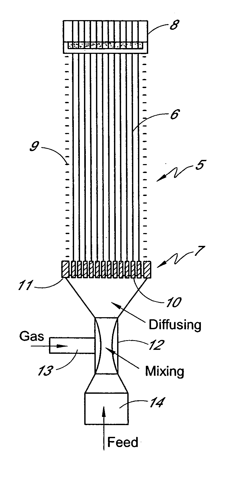
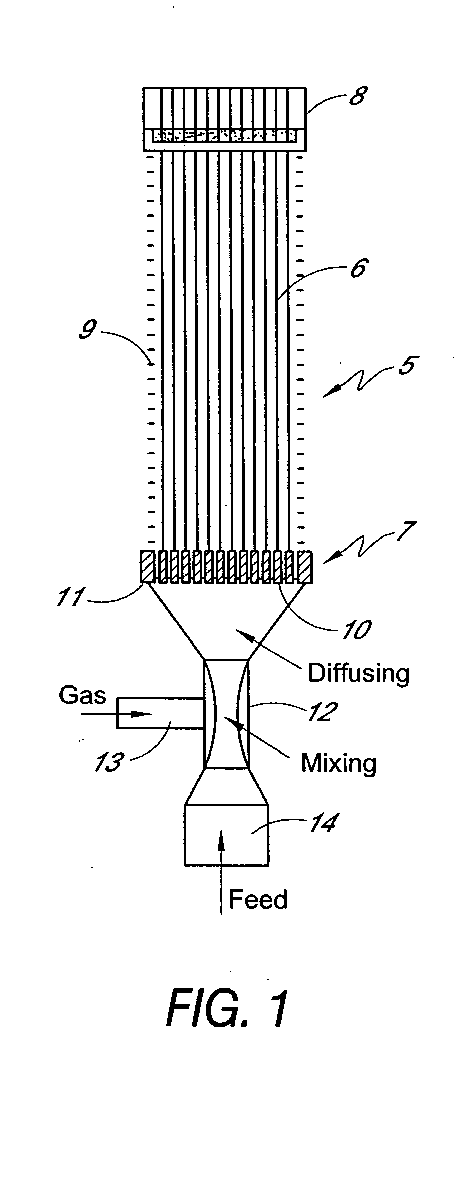
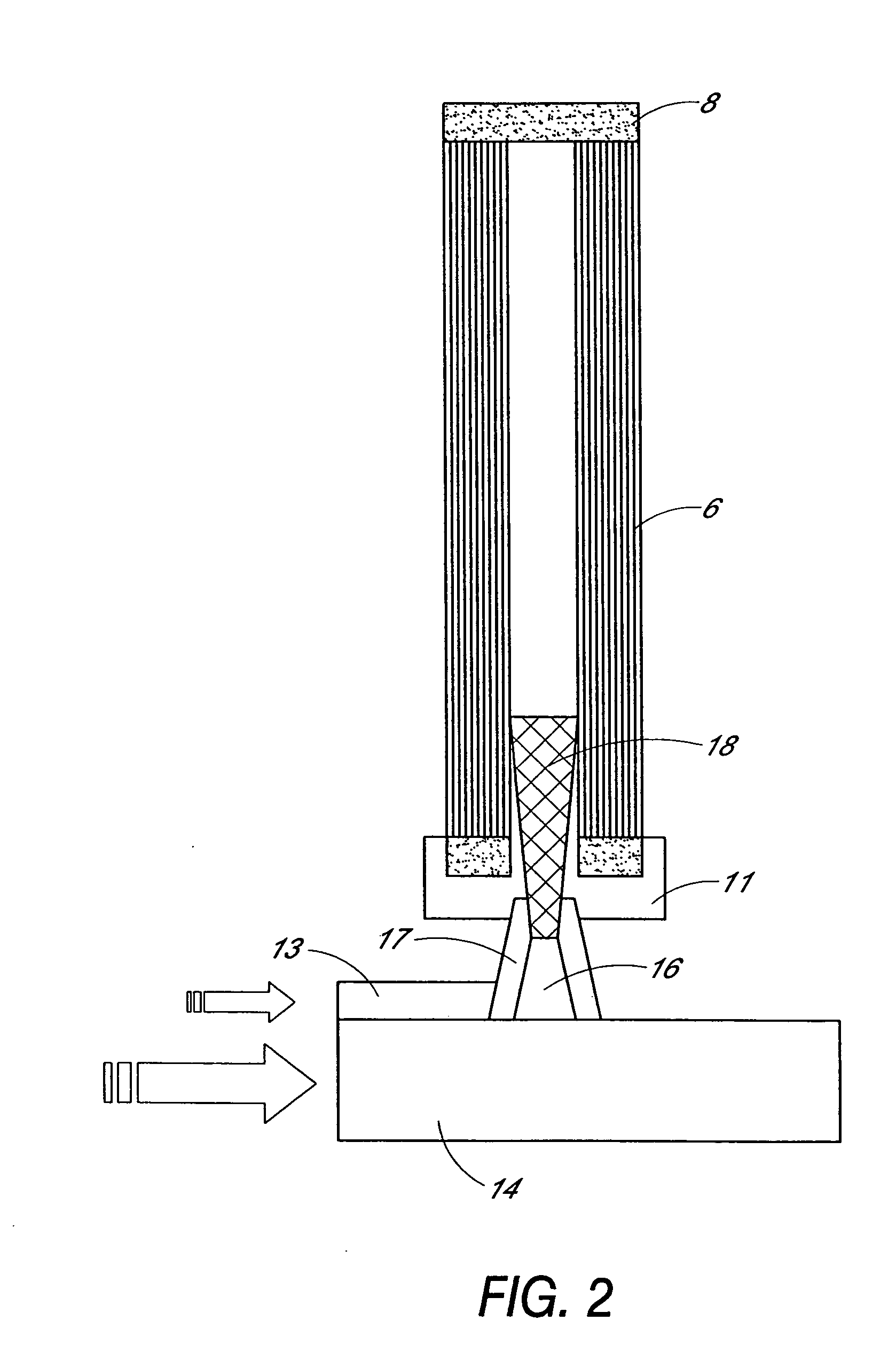
[0041] Referring to the drawings, the embodiments of the invention will be described in relation to a membrane module of the type disclosed in our earlier PCT application No. WO98 / 28066 which is incorporated herein by cross-reference, however, it will be appreciated that the invention is equally applicable to other forms of membrane module. The membrane module 5 typically comprises fibre, tubular or flat sheet form membranes 6 potted at two ends 7 and 8 and encased in a support structure, in this case a screen 9. Either one or both ends of the membranes may be used for the permeate collection. The bottom of the membrane module has a number of through apertures 10 in the pot 11 to distribute a mixture of gas and liquid feed past the membrane surfaces.
[0042] Referring to the embodiment shown in FIG. 1, a venturi device 12 or the like is connected to the base of the module. The venturi device 12 intakes gas through inlet 13, mixes or entrains the gas with liquid flowing through feed i...
PUM
Property
Measurement
Unit
diameter
aaaaa
aaaaa
diameter
aaaaa
aaaaa
diameter
aaaaa
aaaaa
Abstract
A method and apparatus for cleaning a membrane module, the membrane module having a plurality of porous membranes, the membranes being arranged in close proximity to one another and mounted to prevent excessive movement therebetween and means for providing, from within the module, by means other than gas passing through the pores of the membranes, gas bubbles entrained in a liquid flow such that, in use, the liquid and bubbles entrained therein move past the surfaces of the membranes to dislodge fouling materials therefrom, the gas bubbles being entrained in the liquid by flowing the liquid past a source of gas to draw the gas into the liquid flow. The gas bubbles are preferably entrained into the liquid using a venturi type device. The membranes are preferably partitioned into discrete groups to assist cleaning while maintaining high packing density.
Description
RELATED APPLICATIONS [0001] This application is a continuation of application Ser. No. 10 / 822,036, filed Apr. 8, 2004, which is a continuation of application Ser. No. 10 / 428,601, filed May 1, 2003, now U.S. Pat. No. 6,821,420, which is a division of application Ser. No. 10 / 303,447, filed Nov. 21, 2002, now U.S. Pat. No. 6,641,733, which is a continuation of application Ser. No. 09 / 815,966, filed Mar. 23, 2001, now U.S. Pat. No. 6,524,481, which is a continuation under 35 U.S.C. §120 of International Patent Application No. PCT / AU99 / 00817 filed on Sep. 24, 1999, under the Patent Cooperation Treaty (PCT), which was published by the International Bureau in English on April 6, 2000, which designates the United States, and which claims the benefit of Australian Provisional Patent Application No. PP 6217 filed on Sep. 25, 1998, Australian Provisional Patent Application No. PP 6218 filed on Sep. 25, 1998, and Australian Provisional Patent Application No. PQ 1112 filed on Jun. 21, 1999.FIELD...
Claims
Application Information
Patent Timeline
Application Date:The date an application was filed.
Publication Date:The date a patent or application was officially published.
First Publication Date:The earliest publication date of a patent with the same application number.
Issue Date:Publication date of the patent grant document.
PCT Entry Date:The Entry date of PCT National Phase.
Estimated Expiry Date:The statutory expiry date of a patent right according to the Patent Law, and it is the longest term of protection that the patent right can achieve without the termination of the patent right due to other reasons(Term extension factor has been taken into account ).
Invalid Date:Actual expiry date is based on effective date or publication date of legal transaction data of invalid patent.
Patent Type & AuthorityApplications(United States)

