Supercharge Your Innovation With Domain-Expert AI Agents!

Convection cooling techniques in selective deposition modeling

a cooling technique and selective deposition technology, applied in butter manufacture, auxillary shaping apparatus, manufacturing environment conditioning, etc., can solve the problems of heat generation levels and heat generated by uv exposure systems

Active Publication Date: 2005-05-26
3D SYST INC
View PDF17 Cites 13 Cited by
  • Summary
  • Abstract
  • Description
  • Claims
  • Application Information

AI Technical Summary

Benefits of technology

The present invention provides a method and apparatus for cooling a heat generating component in a selective deposition modeling apparatus. The cooling system uses convection heat transfer with a gas medium to remove large amounts of localized heat generated in the SDM apparatus. The cooling system includes a support means, a dispensing means, a flash exposure means, and a cooling system for providing steady state cooling of the flash exposure means. The cooling system utilizes a first gas flow to establish a low-pressure zone which draws a second gas flow into the low pressure zone. The second gas flow is directed over a heat generating component in the SDM apparatus to achieve steady state cooling of the component. The cooling system does not require the use of a liquid heat transfer medium and can provide steady state heat transfer without using high velocity fans. The method involves generating a first flow of air, delivering the first flow of air to a venturi duct, establishing a low-pressure zone in the restriction chamber of the venturi duct, providing a port in the restriction chamber operatively engaging the low-pressure zone, and drawing a second flow of air across the heat generating component. The cooling system can effectively cool the heat generating component and improve the efficiency of the SDM apparatus.

Problems solved by technology

However, UV exposure systems themselves generate significant amounts of heat, whether they are pulse flash systems or continuous flood systems.
Undesirably, the high levels of heat generated by these lamps pose significant problems in SDM.

Method used


Image

  • Convection cooling techniques in selective deposition modeling
  • Convection cooling techniques in selective deposition modeling
  • Convection cooling techniques in selective deposition modeling

Examples


Embodiment Construction

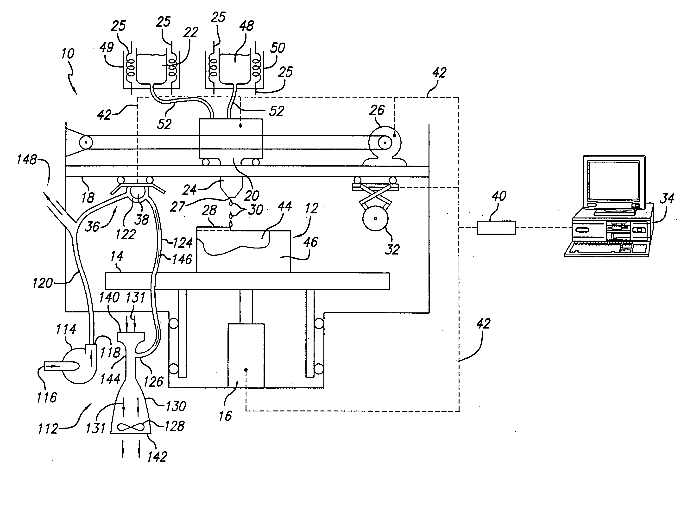
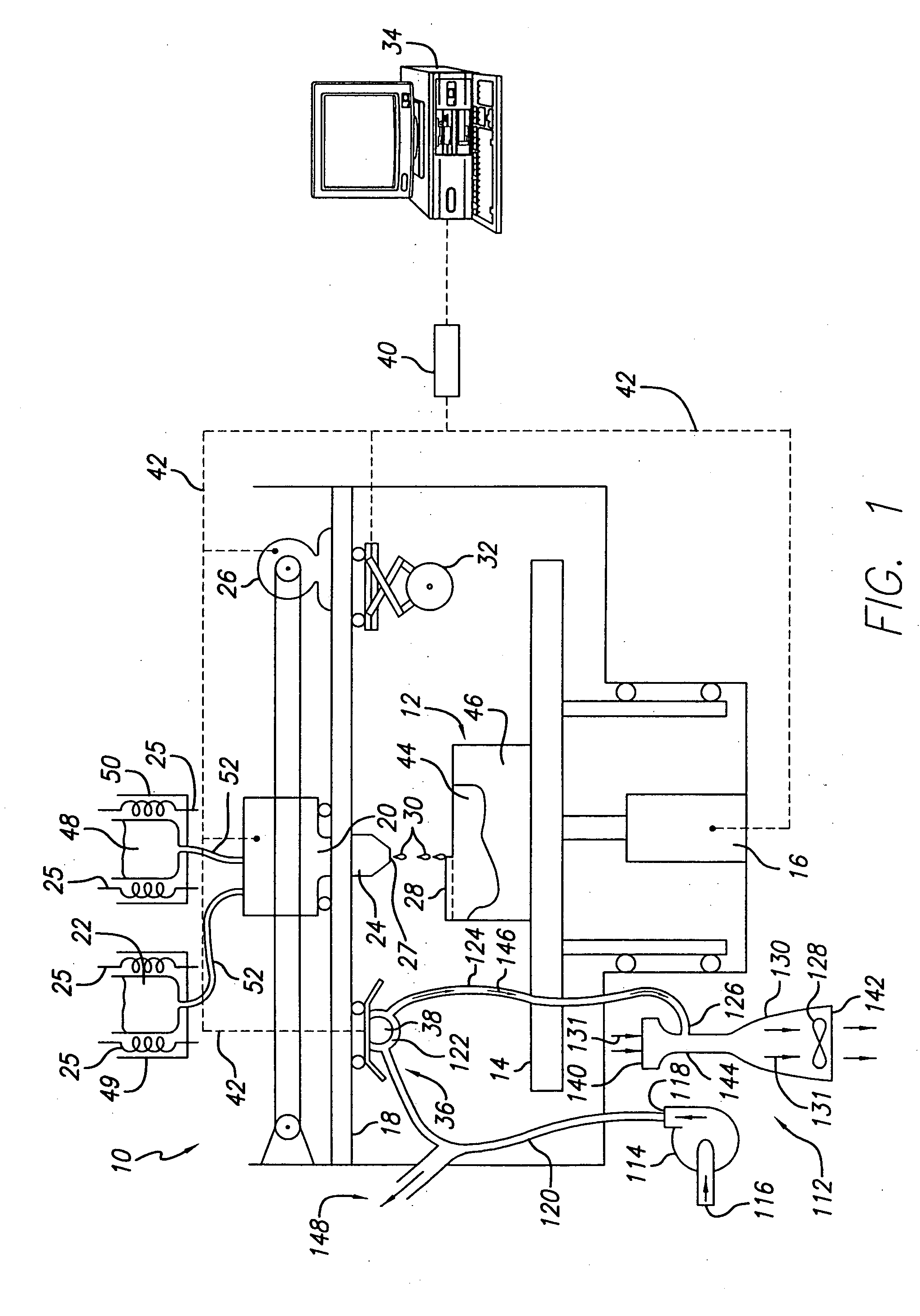
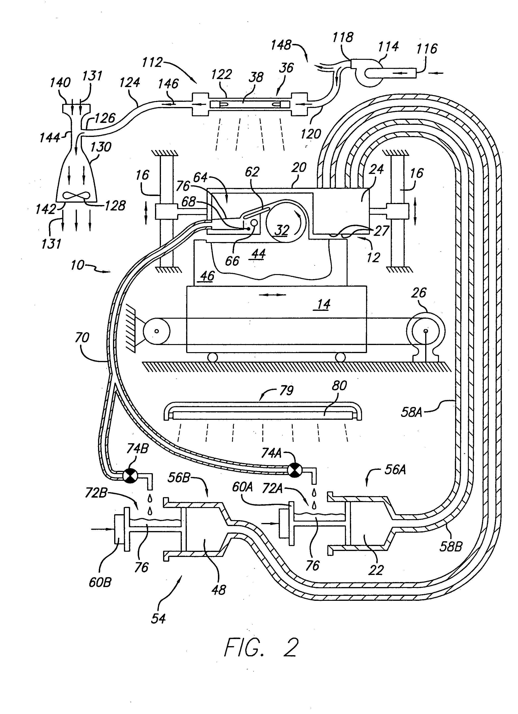
[0026] While the convection cooling technique of the present invention is applicable to all SFF techniques requiring the removal of large amounts of localized heat by convection heat transfer, the invention will be described with respect to an SDM apparatus having a flash exposure system and utilizing an ink jet print head dispensing a curable phase change material. The convection cooling technique utilizes air as a gas medium to provide steady state cooling of a flash lamp in a flash exposure system, although other gas media could be used. However, it is to be appreciated that the cooling technique can be adapted for use with any SFF technique that has at least one heat generating component. Further the heat generating component need not be a flash lamp, but may be a continuous emission lamp, or other heat generating device such as a power supply.

[0027] As used herein, the term “a flowable state” of a build material is a state wherein the material is unable to resist shear stresse...


PUM

PropertyMeasurementUnit
temperatureaaaaaaaaaa
viscosityaaaaaaaaaa
surface areaaaaaaaaaaa

Abstract

A convection cooling technique for selective deposition modeling utilizing a venturi duct to establish a low-pressure port for drawing a second flow of air into the duct. The second flow of air is drawn across a heat generating component in the selective deposition modeling apparatus. A low-pressure zone is established at the low-pressure port sufficient to meet the head loss that results when drawing the second flow across the heat generating component and into the venturi duct. A desired flow rate is achieved at a pressure drop that is greater than that possible by the direct use of a fan. The cooling system is well suited for use in providing steady state cooling of radiation exposure systems used in selective deposition modeling to initiate curing of the layers of dispensed material.

Description

BACKGROUND OF THE INVENTION [0001] 1. Field of the Invention [0002] The invention relates in general to solid deposition modeling, and in particular to a method and apparatus for providing steady state convection cooling in solid deposition modeling apparatus for a heat generating component such as a radiation emitting lamp. [0003] 2. Description of the Prior Art [0004] Recently, several new technologies have been developed for the rapid creation of models, prototypes, and parts for limited run manufacturing. These new technologies are generally called Solid Freeform Fabrication techniques, and are herein referred to as “SFF.” Some SFF techniques include stereolithography, selective deposition modeling, laminated object manufacturing, selective phase area deposition, multi-phase jet solidification, ballistic particle manufacturing, fused deposition modeling, particle deposition, laser sintering, and the like. Generally in SFF techniques, complex parts are produced from a modeling ma...

Claims


Application Information

Patent Timeline
Patent Type & Authority Applications(United States)
IPC IPC(8): B29C35/08G03F7/20B29C35/16B29C41/46B29C41/52B29C67/00
CPCB29C35/0805B29C35/16B29C41/46B29C41/52B29C2035/1658B29C67/0085B29C2035/0827B29C2035/0833B29C67/0059B29C64/112B33Y40/00B33Y30/00B29C64/364B29C64/25
Inventor FONG, JON JODY
Owner 3D SYST INC
Features
  • R&D
  • Intellectual Property
  • Life Sciences
  • Materials
  • Tech Scout
  • Unparalleled Data Quality
  • Higher Quality Content
  • 60% Fewer Hallucinations
Learn More