[0029] Now, a preferred embodiment of the present invention will be described in detail with reference to the accompanying drawings.
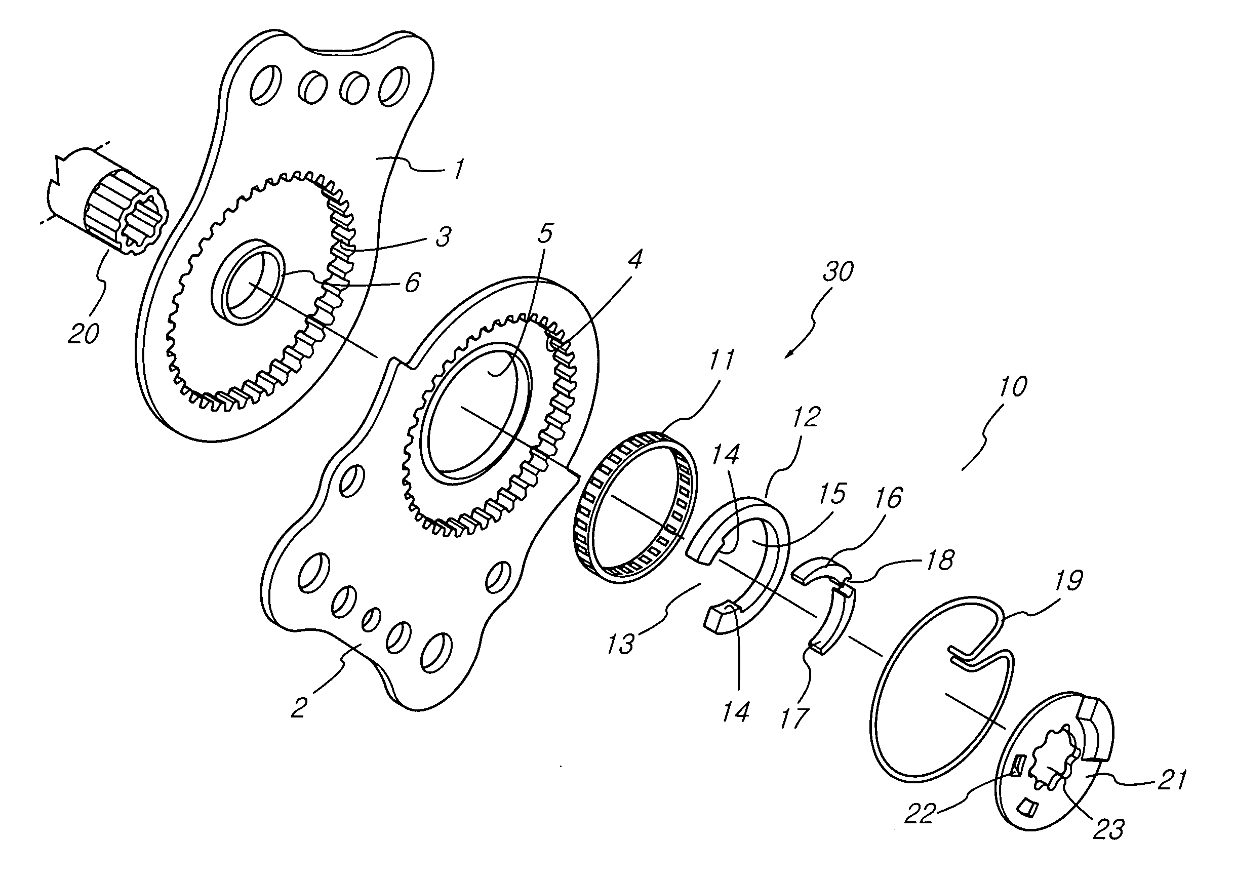
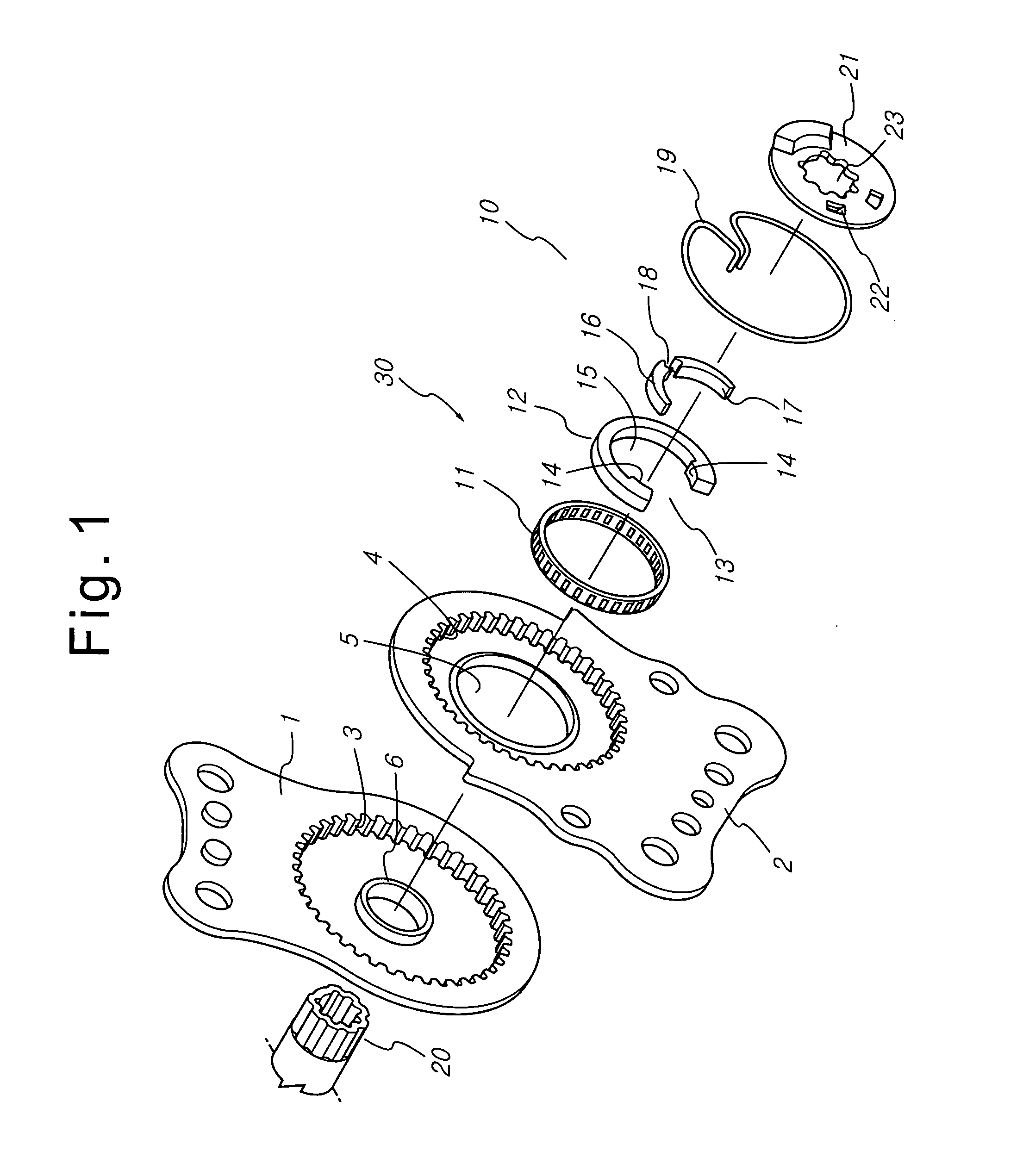
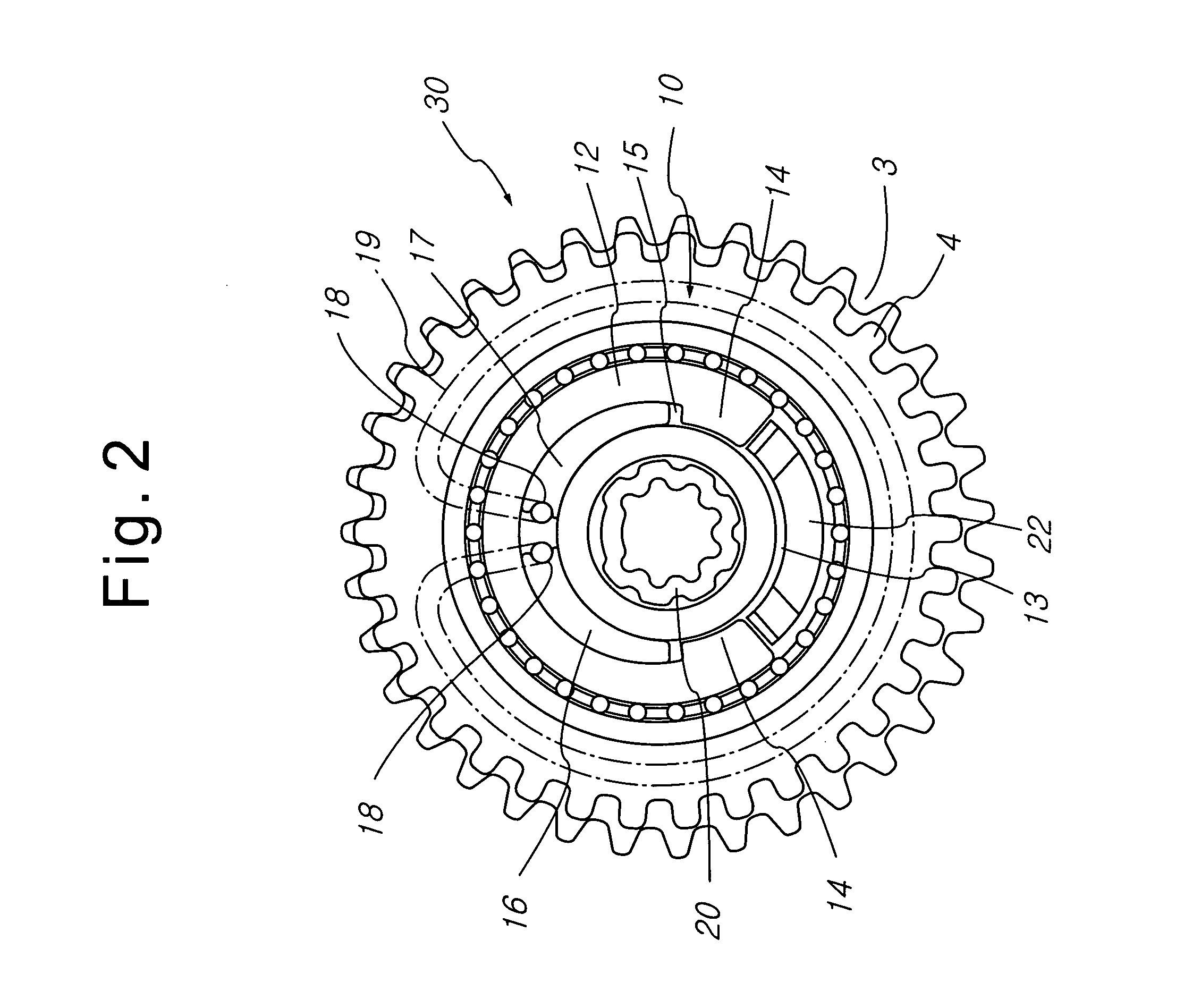
[0030]FIG. 4 is an exploded perspective view showing a continuously operable seat-reclining device 50 for vehicles according to a preferred embodiment of the present invention, FIG. 5 is a front view showing the continuously operable seat-reclining device 50 for vehicles according to the preferred embodiment of the present invention when the continuously operable seat-reclining device for vehicles is assembled, FIG. 6 is a cross-sectional view of the continuously operable seat-reclining device 50 for vehicles according to the preferred embodiment of the present invention taken along line A-A of FIG. 5, FIG. 7 is a front view of the continuously operable seat-reclining device 50 for vehicles according to the preferred embodiment of the present invention showing main components exposed when the continuously operable seat-reclining device for vehicles is assembled, FIG. 8 is a cross-sectional view showing main components of the continuously operable seat-reclining device 50 for vehicles according to the preferred embodiment of the present invention when the continuously operable seat-reclining device for vehicles is not operated; and FIG. 9 is a cross-sectional view showing main components of the continuously operable seat-reclining device 50 for vehicles according to the preferred embodiment of the present invention when the continuously operable seat-reclining device for vehicles is operated.
[0031] The continuously operable seat-reclining device 50 comprises: an upper teeth bracket 51 and a lower teeth bracket 52 securely fixed to a seat back frame and a cushion frame, which together constitute a seat of a vehicle, respectively.
[0032] The upper teeth bracket 51 is provided with upper teeth 53, and the lower teeth bracket 52 is provided with lower teeth 54. The upper teeth 53 of the upper teeth bracket 51 are engaged with the lower teeth 54 of the lower teeth bracket 52. The number of the lower teeth 54 is less than that of the upper teeth 53.
[0033] At the center of the lower teeth bracket 52 is formed a cam hole 55, and at the upper teeth bracket 51 is formed a cam-maintaining ring 56, which is protruded toward the lower teeth bracket 52.
[0034] Between the cam hole 55 and the cam-maintaining ring 56 is disposed an actuator 60 that moves the upper teeth bracket 51 relative to the lower teeth bracket 52 so that a reclining operation is substantially carried out.
[0035] The actuator 60 comprises: a slide bearing 61 disposed around the cam-maintaining ring 56 for reducing a frictional force, and thus improving the reclining operation; and a cam 62 disposed inside the slide bearing 61.
[0036] The cam 62 is formed in the shape of a circle such that the center P of the cam 61 comes in contact with the inner circumference of the slide bearing 61. Also, the cam 62 has a predetermined eccentricity P2 to the center P1 of the cam-maintaining ring 56. An operating surface 63 of the cam 62, to which an actuating force is transmitted, is protruded as compared to a non-operating surface 64 of the cam 62. Consequently, friction between the slide bearing 61 and of the cam 62 does not occur at the non-operating surface 64 of the cam 62.
[0037] Inside the cam 62 is formed a wedge groove 65, in which are disposed arch-shaped wedge blocks 66 and 67 that restrict the operation of the cam 62 to control the movement of the upper teeth bracket 51.
[0038] Along the inner circumference of the wedge groove 65 is partially formed a release projection 68, of which the diameter is slightly greater than the outer diameter of the cam-maintaining ring 56. The release projection 68 comes into contact with the ends of the wedge blocks 66 and 67 to release the wedge blocks 66 and 67.
[0039] The wedge blocks 66 and 67 are formed such that the sizes of the wedge blocks 66 and 67 are decreased toward the outer ends of the wedge blocks 66 and 67 from the center of the cam-maintaining ring 56. Consequently, the wedge blocks 66 and 67 have eccentricities. Preferably, a tangential angle θ of the wedge block 66 or 67 to the cam-maintaining ring 56 is as small as possible.
[0040] This is because the tangential angle θ, which is formed by a connecting point WP where the cam-maintaining ring 56 comes in contact with the wedge block 66 or 67 and a middle point MP between the opposite inner ends of the wedge blocks 66 and 67, multiplied by a spring force SP equals wedge efficiency.
[0041] At the opposite inner ends of the wedge blocks 66 and 67 are formed spring grooves 69, respectively. In the spring grooves 69 are disposed wedge springs 70 that increase the distance between the wedge blocks 66 and 67.
[0042] To the outside of the cam 62 is attached a coupling 72, which is fixed to a shaft 71 disposed at the rear of the upper teeth bracket 51. To the coupling 72 is attached a driving unit, such as a lever or a motor, that drives the cam 62.
[0043] At the outside of the cam 62 are formed a plurality of actuating protrusions 73, which are spaced apart from each other in the radial direction, and at the coupling 72 are formed a plurality of protrusion-fitting grooves 74, in which the actuating protrusions 73 are fitted, respectively. Consequently, a moment-transmitting force of the shaft 71 is uniformly dispersed, whereby smooth operation is guaranteed. Also, the frictional area of the cam 62 is increased, whereby the durability of the cam 62 is improved.
[0044] Preferably, the shaft 71 and a shaft hole 75 formed at the coupling 72, through which the shaft 71 is inserted, are formed in directional shapes such that the shaft 71 can be easily inserted through the shaft hole 75 of the coupling 72, the shaft 71 is prevented from being wrongly connected with the opposite recliner, and a rotary moment is easily transmitted by means of the shaft 71.
[0045] The directional shapes of the shaft 71 and the shaft hole 75 are not restricted. For example, the shaft 71 and the shaft hole have directional shapes formed by removing one of splines, which are uniformly spaced apart from each other, from the other splines.
[0046] The operation of the seat-reclining device 50 according to the present invention will be described hereinafter in detail.
[0047] The seat-reclining device 50 is switched between a non-operating state and an operating state. The operating state of the seat-reclining device 50 is the state in that the back of a seat is angularly moved forward or backward.
[0048] In the non-operating state, the distance between the opposite inner ends of the wedge blocks 66 and 67 inserted in the wedge groove 65, which is formed at the inside of the cam inserted in the cam hole 55, which is formed at the lower teeth bracket 52, is widened toward the release projections 68 formed at the cam 62 by means of wedge springs 70. As a result, the movement of the cam 62 is restricted.
[0049] Also, a gap between the center P of the cam 62 and the center P1 of the cam-maintaining ring 56, i.e., eccentricity P2, is eliminated, whereby the cam 62 is prevented from being moved. Consequently, no gap is generated between the upper teeth 53 and the lower teeth 54.
[0050] Since no gap is generated between the upper teeth 53 and the lower teeth 54 as described above, the back of the seat is not moved while the seat-reclining device is not operated, and therefore noise is not generated due to the operation of the seat-reclining device. Consequently, pleasant ride comfort is maintained.
[0051] When the seat-reclining device 50 is to be operated, a lever protruded from one side of the seat while being attached to the coupling 72 or a switch that controls the motor connected to the coupling 72 is manipulated such that the back of the seat is angularly moved forward or backward.
[0052] As the coupling 72 is rotated in the direction in which the back of the seat is to be angularly moved forward or backward, the cam 62 is rotated in the direction in which the back of the seat is to be angularly moved forward or backward, since the actuating protrusions 73, which are formed at the outside of the cam 62 such that the actuating protrusions 73 are protruded from the outside of the cam 62, are fitted in the protrusion-fitting grooves 74, which are radially formed at the coupling 72.
[0053] The cam 62 is rotated by the distance between the cam 62 and the wedge block 66 and 67 disposed in the rotating direction. As a result, the wedge block 66 or 67 is pushed by means of the release projection 68 formed at the inside of the cam 62, whereby the locked state of the wedge blocks 66 and 67 is released.
[0054] As the coupling 72 is continuously rotated in the direction in which the back of the seat is to be angularly moved forward or backward, the locked state of the wedge blocks 66 and 67 is released by means of the cam 62. Consequently, the reclining operation is continuously carried out.
[0055] At this time, the actuating force of the cam 62 is transmitted to the upper teeth bracket 51 through the slide bearing 61 disposed in the cam hole 55. The upper teeth bracket 51 is rotated in the forward or reverse direction relative to the lower teeth bracket 52 to move pitches corresponding to the difference, in the number of teeth, between the upper teeth 53 and the lower teeth 54. Consequently, the reclining operation is continuously carried out.
[0056] When the back of the seat is to be angularly moved in the opposite direction, the actuating unit is manipulated such that the actuating unit is rotated in the opposite direction.
[0057] In the case that the recliner is mounted to the opposite side, the eccentric directions of the cam 62 and the wedge blocks 66 and 67 are constantly maintained, since the shaft hole 75 formed at the coupling 72 and the shaft 71 inserted through the shaft hole 75 are formed in directional shapes such that the shaft 71 can be easily inserted through the shaft hole 75 of the coupling 72, the shaft 71 is prevented from being wrongly connected with the opposite recliner, and a rotary moment is easily transmitted by means of the shaft 71. Consequently, the synchronous operation is possible.
[0058] According to the present invention, the rotary moment transmitted to the coupling 72 through the shaft 71 is dispersed to several points by means of the protrusion-fitting grooves 74 and the actuating protrusions 73 radially formed at the coupling 72 and the cam 62, respectively. Consequently, the rotary moment is prevented from being concentrated.
[0059] As described above, the rotary moment of the shaft is uniformly transmitted to the coupling 72 and the cam 62 through the multi-point dispersion, and thus the smooth operation of the cam is guaranteed. As a result, the frictional area between the cam 62 and the slide bearing 61 that moves the upper teeth bracket 52 is increased, whereby reliable operation of the cam is guaranteed.
[0060] Especially, the cam 62 according to the present invention is formed in the shape of a circle such that the cam 62 is stably disposed in the cam hole 55. Also, the stable operation of the cam 62 is guaranteed by means of the slide bearing 61 disposed on the outer circumference of the cam 62. Consequently, easier operation is carried out.
[0061] As apparent from the above description, the present invention provides a continuously operable seat-reclining device having an improved actuator to substantially carry out a reclining operation of the reclining device such that an actuating force of a shaft is uniformly transmitted to the entirety of a coupling that moves a cam while the actuator is not affected by vibration, whereby actuating load is reduced, and thus the smooth operation of the seat-reclining device is accomplished while the quality of the seat-reclining device is improved, and convenience of use is improved.
[0062] Although the preferred embodiment of the present invention has been disclosed for illustrative purposes, those skilled in the art will appreciate that various modifications, additions and substitutions are possible, without departing from the scope and spirit of the invention as disclosed in the accompanying claims.