

Modular assembly for a self-indexing computer pointing device
a self-indexing, computer technology, applied in the direction of hinge/pivot support structure, cathode-ray tube indicator, instruments, etc., can solve the problems of not being able to meet the above requirements, not being able to achieve similar success devices for portable and hand-held computers, and only a small amount of button movemen
- Summary
- Abstract
- Description
- Claims
- Application Information
AI Technical Summary
Benefits of technology
Problems solved by technology
Method used
Image

Examples
Embodiment Construction
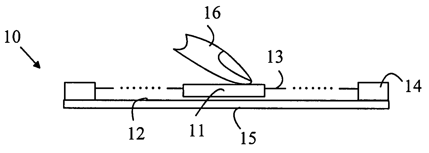
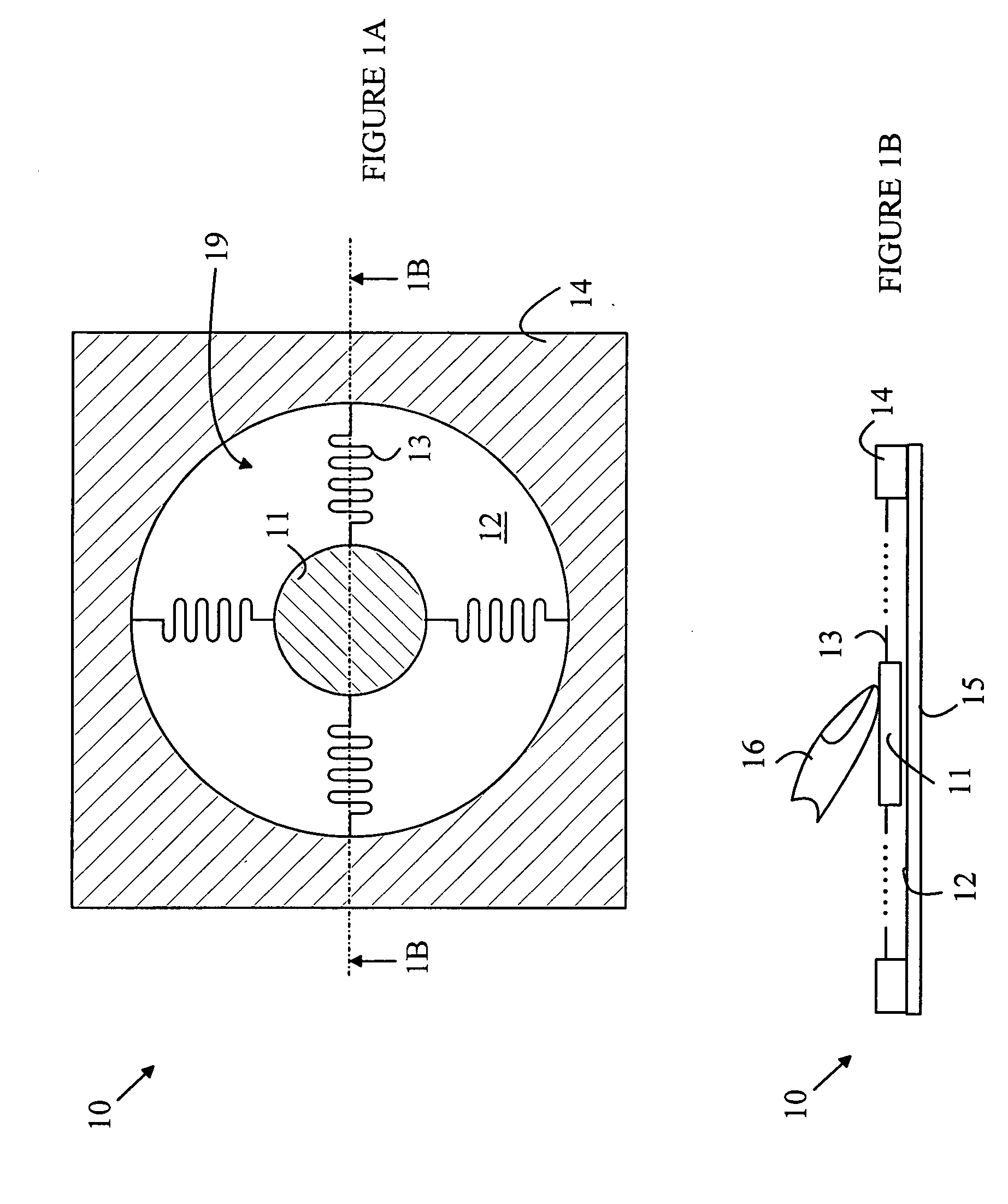
[0022] The manner in which the present invention provides its advantages can be more easily understood with reference to FIGS. 1A-1B, which illustrate a puck based pointing device 10. FIG. 1A is a top view of pointing device 10 and FIG. 1B is a cross-sectional view of pointing device 10 through line 1B-1B shown in FIG. 1A. Pointing device 10 includes a puck 11 that moves over a surface 12 of a substrate 15 within a puck field of motion 19 in response to a lateral force applied to puck 11. The force is typically applied to puck 11 by a user's finger, fingertip, thumb, thumb tip or multiple fingers. Puck 11 includes a pressure sensing mechanism that measures the vertical pressure applied to puck 11. In addition, pointing device 10 includes a sensing mechanism for determining the position of puck 11 on surface 12.
[0023] The puck is typically used to control a cursor on a display. When the user applies a vertical force to puck 11 that is greater than a predetermined threshold, any chan...
PUM
 Abstract
Description
Claims
Application Information