Hydroelectric coupling for a printhead and a printer equipped with one such coupling

a technology of hydroelectric coupling and printhead, which is applied in the direction of printing, other printing apparatus, etc., can solve the problems of practicably not being able to disassemble the umbilical without causing damage, and achieve the effects of reducing electrical insulation problems, simplifying the integration of high-voltage power supply in the print head, and reducing deflection performan

Inactive Publication Date: 2005-05-26
MARKEM IMAJE LTD
View PDF10 Cites 22 Cited by
  • Summary
  • Abstract
  • Description
  • Claims
  • Application Information

AI Technical Summary

Benefits of technology

The invention simplifies the process of creating high voltage for ink drop deflection electrodes by using low voltage sources and electrical circuits housed inside a print head casing. This reduces insulation problems and allows for a small and constant inter-electrode spacing, resulting in improved deflection performance with lower voltage. This simplifies the integration of the high voltage power supply in the print head and reduces electrical insulation problems.

Problems solved by technology

The technical problem addressed in this patent is the difficulty and complexity of connecting the electrical and hydraulic fittings of a print head in a continuous jet printer. The patent proposes a solution to simplify the assembly and disassembly process.

Method used


Image

  • Hydroelectric coupling for a printhead and a printer equipped with one such coupling
  • Hydroelectric coupling for a printhead and a printer equipped with one such coupling
  • Hydroelectric coupling for a printhead and a printer equipped with one such coupling

Examples


Embodiment Construction

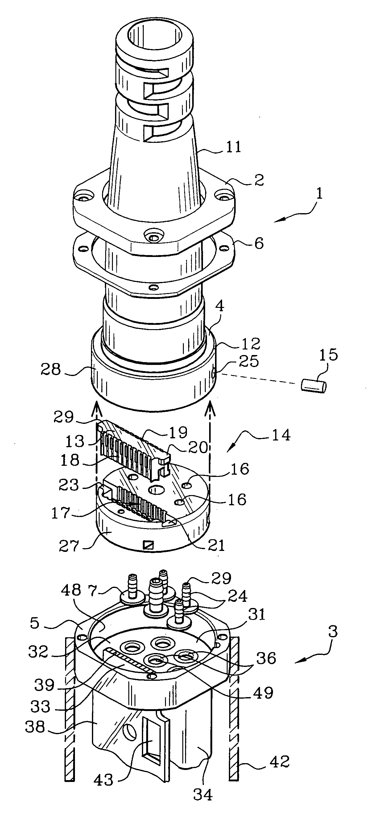
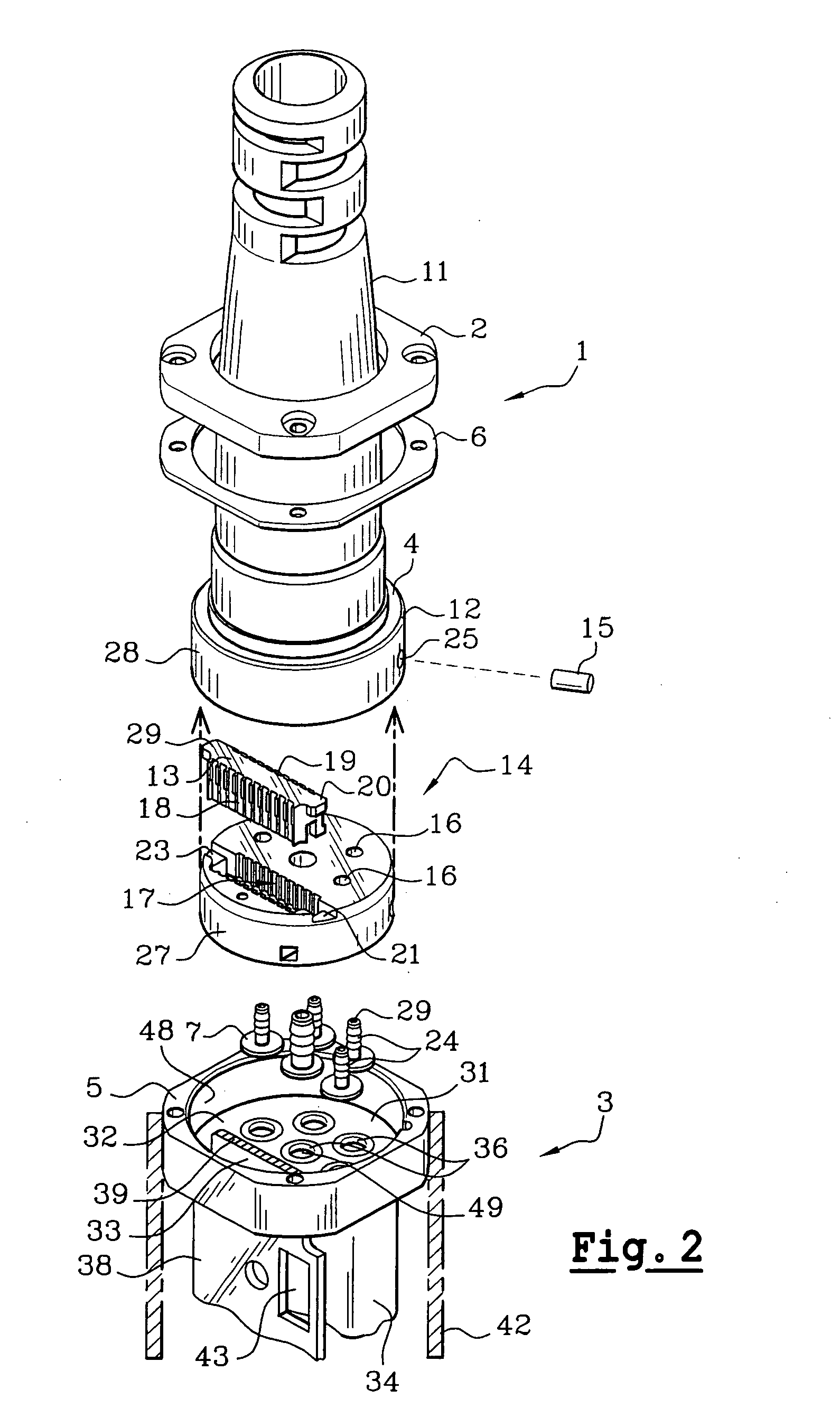
[0034]FIG. 2 shows an exploded perspective view of a terminal connection part 1 of an umbilical and the connection part 3 of a printer print head.

[0035] The electrical and hydraulic terminal parts of the umbilical are known in themselves and are not shown, so that attention can be concentrated on the invention itself.

[0036] The terminal part 1 of the umbilical comprises an enclosure 11 housing the terminal parts of the electrical conductors and hydraulic pipes, in a manner known in itself.

[0037] In accordance with the invention, a hollow rigid terminal part 12 referred to as the bell 12 of the enclosure 11 in the following description contains means 13 and 14 for positioning the electrical terminal parts, and means 14 for positioning the hydraulic terminal parts. This bell includes a hollow part that cannot be seen in FIG. 2, provided with a flat bottom 4, the centre of which is drilled to allow hydraulic pipes and electrical conductors contained in the umbilical to pass through ...


PUM


Abstract

An ink jet printer is characterised in that a connection part (1) of an umbilical connected to a connection part of a print head of the printer, comprises:
    • first (12, 13, 14, 15, 17, 18, 20-23, 25) and second means (12, 14, 15, 16, 25) for positioning the umbilical electrical terminations (13, 19) and hydraulic terminations (24) mechanically fixed to the connection part (1) of the umbilical;
    • third (12, 28) positioning means mechanically connected to the umbilical, and fourth positioning means (31, 48) mechanically connected to the connection part (3) of the print head,
    • the third (12, 28) positioning means and the fourth positioning means (31, 48) cooperating to position the connection part (1) of the umbilical with respect to the connection part (3) of the print head. A translation movement alone is necessary to connect the umbilical onto the print head.

Description


Claims


Application Information

Patent Timeline
Owner MARKEM IMAJE LTD
Why Eureka
Try Eureka