
Imaging surveillance system and method for event detection in low illumination

a surveillance system and low illumination technology, applied in the field of surveillance systems, can solve the problems of disturbing both the occupants of the property and their neighbors, the sensitivity of digital cameras is limited, and the source of artificial illumination is required,

Active Publication Date: 2005-05-26
APTINA IMAGING CORP
View PDF8 Cites 78 Cited by
  • Summary
  • Abstract
  • Description
  • Claims
  • Application Information

AI Technical Summary

Benefits of technology

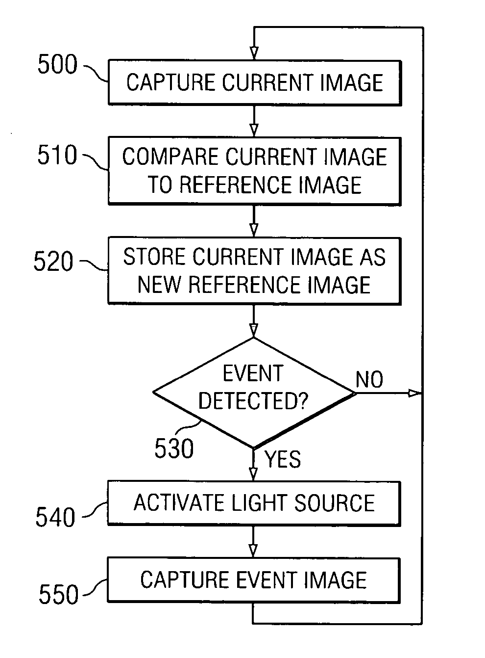
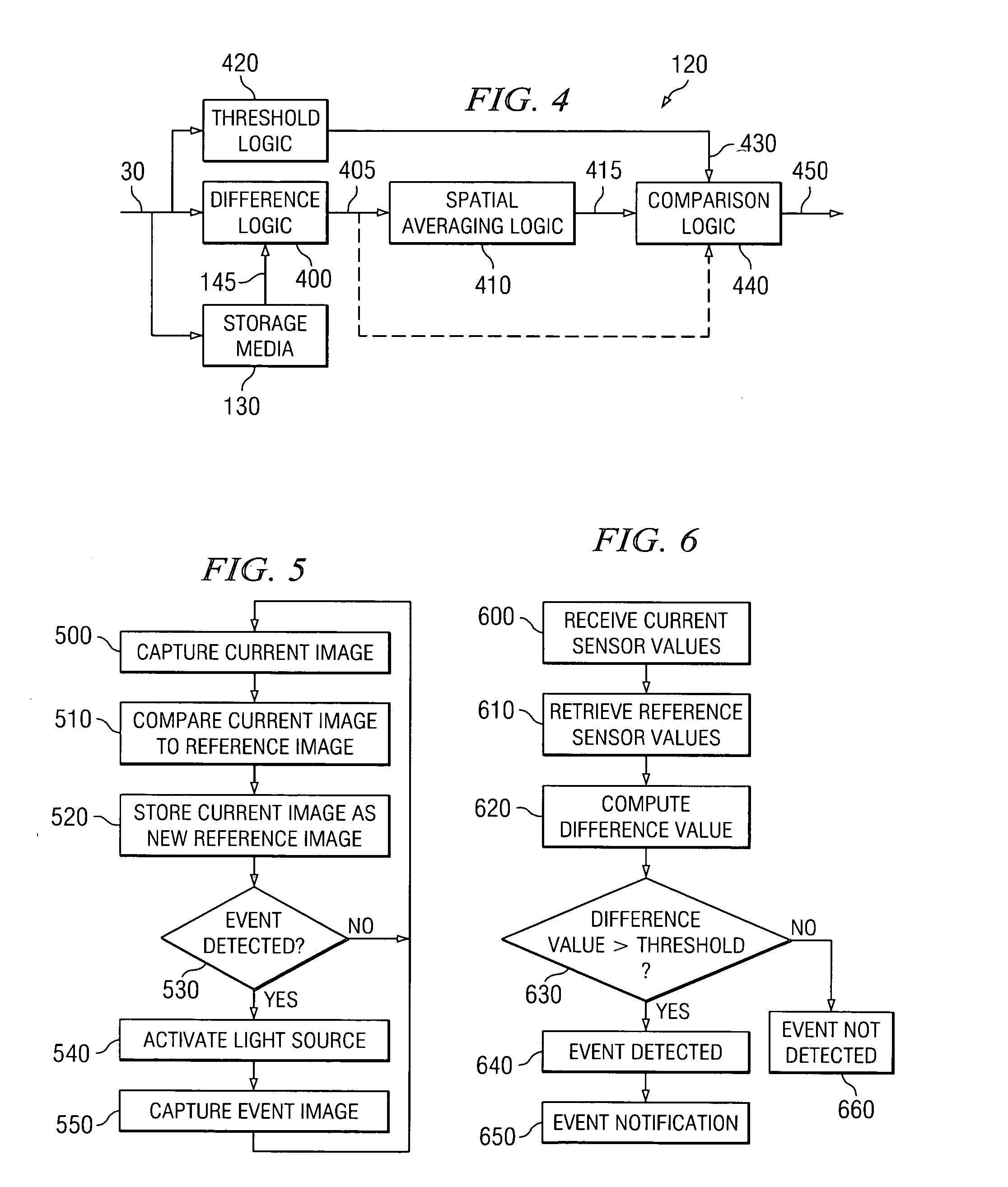
"The present invention provides a surveillance system and method for detecting an event and capturing an image of the event under low illumination conditions. The camera is configured to capture a current image and compare it to a reference image previously captured under similar low illumination conditions. The camera is further configured to determine, based on the results of the comparison, whether an event has occurred in the current image. The current image and reference image are captured using long exposure times to enable the camera to receive sufficient light in the low illumination conditions. An illumination source is connected to the camera and activated upon the detection of an event to provide sufficient artificial illumination to capture one or more additional event images using a shorter exposure time. The event image(s) can be stored internally within the camera or transmitted to an external security system for storage and / or analysis. The invention enables a surveillance camera to operate under low illumination conditions without consuming excessive power."

Problems solved by technology

However, digital cameras have limited sensitivity, and in areas of low illumination or at night, a source of artificial illumination is required.
However, in residential applications, lights that are left on at night can be disturbing to both the occupants of a property and their neighbors.
In addition, if a illumination source is attached to a battery-powered camera, constant illumination would reduce the life of the battery, necessitating frequent battery replacements.

Method used


Image

  • Imaging surveillance system and method for event detection in low illumination
  • Imaging surveillance system and method for event detection in low illumination
  • Imaging surveillance system and method for event detection in low illumination

Examples


Embodiment Construction

[0017] The numerous innovative teachings of the present application will be described with particular reference to exemplary embodiments. However, it should be understood that these embodiments provide only a few examples of the many advantageous uses of the innovative teachings herein. In general, statements made in the specification do not necessarily delimit any of the various claimed inventions. Moreover, some statements may apply to some inventive features, but not to others.

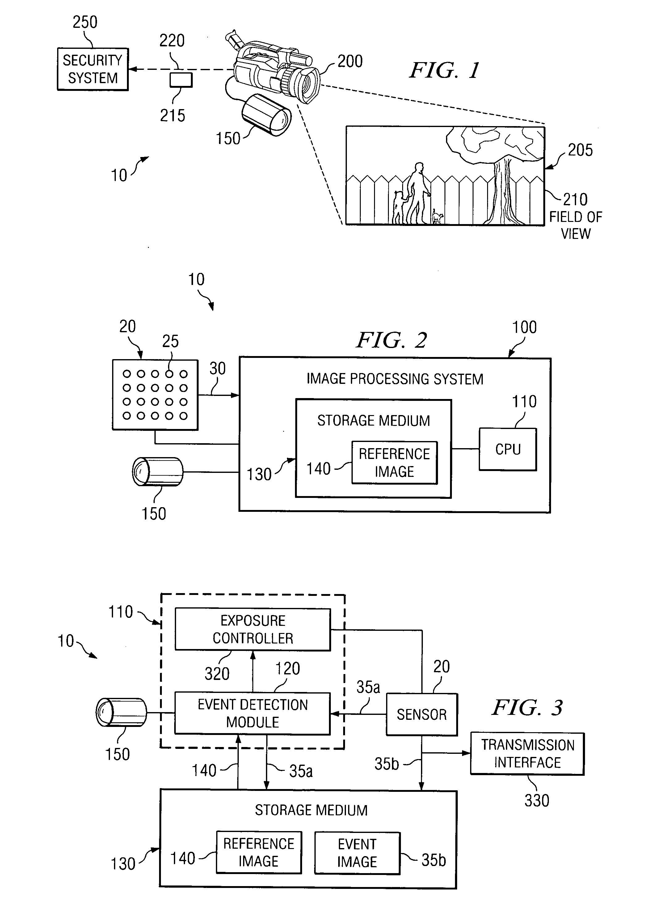
[0018]FIG. 1 illustrates a surveillance system 10 capable of operating under low illumination conditions, in accordance with embodiments of the present invention. The surveillance system 10 uses a camera 200, such as a digital camera, or other type of imaging sensor device to monitor the activity of targets in a scene 205 by capturing one or more images of the scene 205. The scene 205 that the surveillance system 10 monitors depends on a field-of-view 210 of the camera 200, which is determined, at least in...


PUM


Abstract

A surveillance system and method is provided for detecting and event and then capturing an image of the event under low illumination conditions. A camera captures a current image and a prior reference image under low illumination conditions using a long exposure time and compares the current and reference images to determine whether an event has occurred in the current image. An illumination source is activated upon the detection of an event to provide artificial illumination. The illumination allows an additional event image to be captured using a shorter exposure time.

Description

BACKGROUND OF THE INVENTION [0001] 1. Technical Field of the Invention [0002] The present invention relates generally to surveillance systems, and specifically to event detection using images captured by surveillance systems. [0003] 2. Description of Related Art [0004] Surveillance systems commonly employ video cameras to monitor facilities. Historically, these cameras have transmitted analog video images of an area under surveillance to a security monitoring center for inspection and storage. In many facilities, analog video cameras are being replaced with digital cameras that detect and capture still images of events, such as the appearance of an intruder, a malfunction, or a fire within the area under surveillance. Digital cameras provide several advantages over analog video cameras. For example, digital cameras can be radio linked and battery powered to eliminate the need for the costly fixed infrastructure of video cables and power lines, making surveillance systems cheaper and...

Claims


Application Information

Patent Timeline
Patent Type & Authority Applications(United States)
IPC IPC(8): G06T7/20H04N7/18
CPCH04N7/188G06T7/254
Inventor BAER, RICHARD
Owner APTINA IMAGING CORP
Learn More