
Fluid compressor

a compressor and fluid technology, applied in the field of fluid compressors, can solve the problems of lowering fuel efficiency of hydrogen gas, high humidity of hydrogen off gas, and interference with normal activation of fuel cells

Inactive Publication Date: 2005-05-26
TOYOTA IND CORP
View PDF4 Cites 20 Cited by
  • Summary
  • Abstract
  • Description
  • Claims
  • Application Information

AI Technical Summary

Problems solved by technology

The discharge of such hydrogen gas lowers fuel efficiency.
In such a case, however, the humidity of the hydrogen off gas would be high.
Activation of the fuel cell when water is frozen in such a manner would interfere with normal activation of the fuel cell.
This problem may occur in any system in which liquid collects in a pump chamber.
As a result, in the root pump described in Japanese Laid-Open Patent Publication No. 8-109888, the residual water would freeze under a low temperature atmosphere and interfere with normal activation of the pump.

Method used


Image

  • Fluid compressor
  • Fluid compressor
  • Fluid compressor

Examples


Embodiment Construction

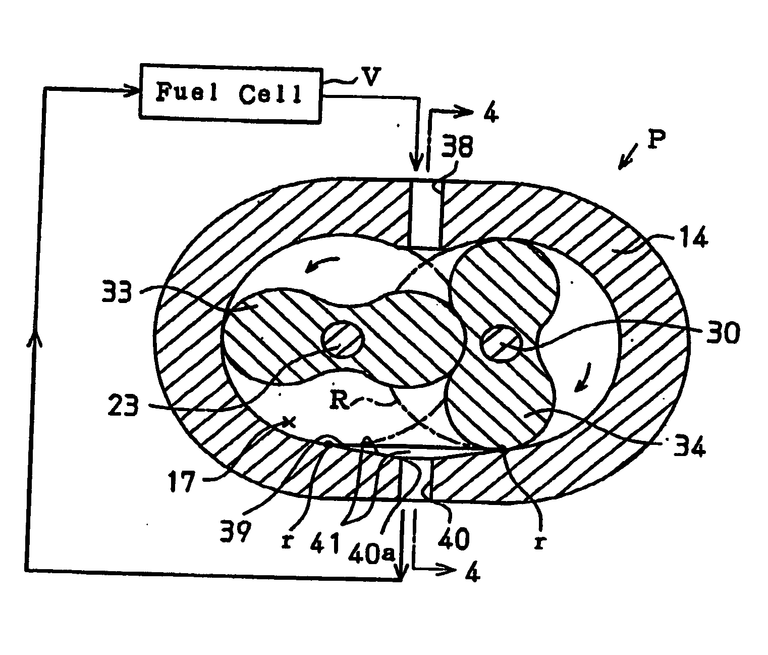
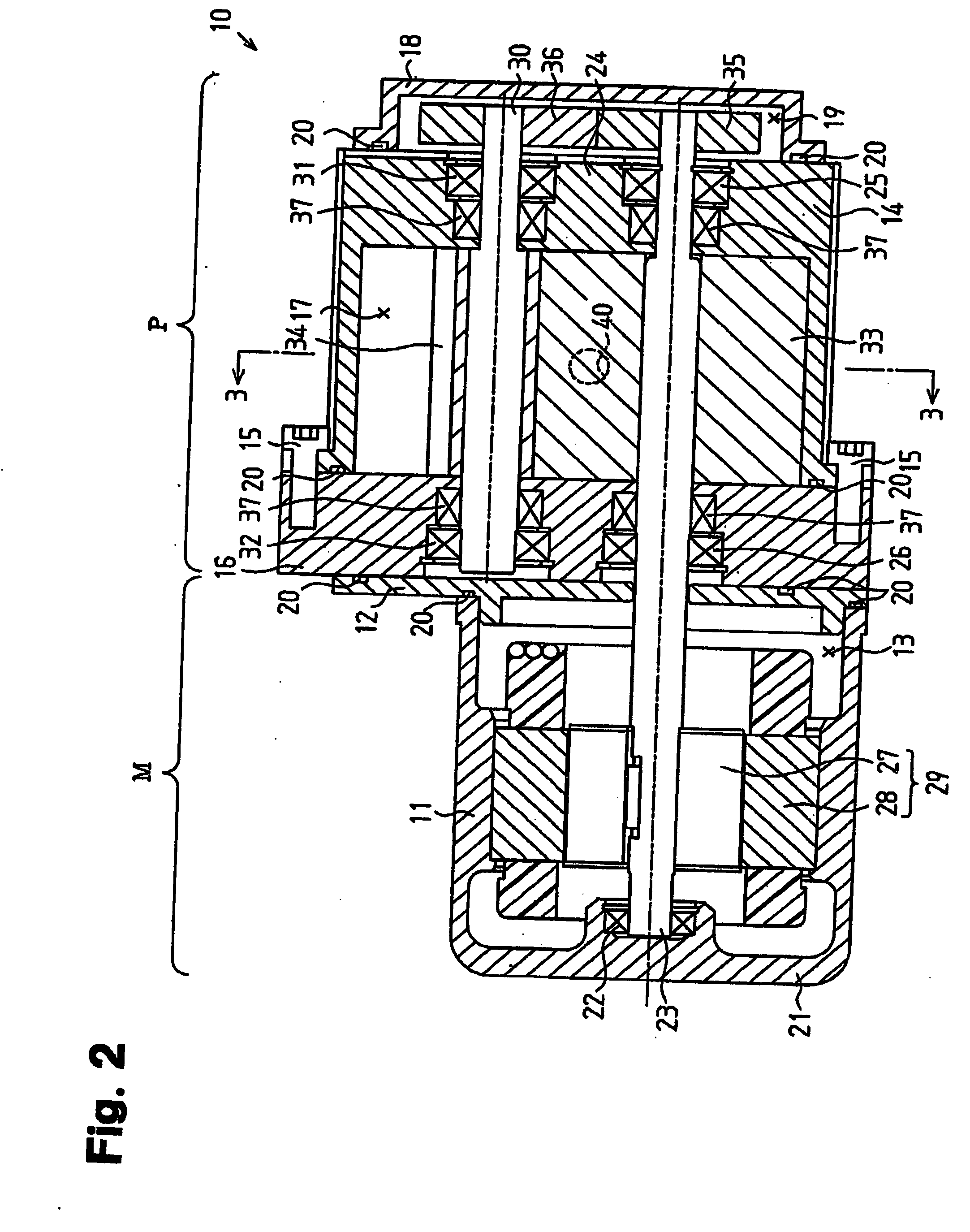
[0017] A hydrogen compressor 10 according to a preferred embodiment of the present invention will now be described with reference to FIGS. 2 to 4. The hydrogen compressor 10 is one type of fluid compressor that is used in a fuel cell system.

[0018] Referring to FIG. 2, in the preferred embodiment, the hydrogen compressor 10 includes a motor M and a root pump P. The motor M includes a motor housing 11, which is cylindrical, and a partition wall 12. The motor housing 11 has a closed first end (left end as viewed in FIG. 2) and an open second end (right end as viewed in FIG. 2). The partition wall 12 is coupled to the motor housing 11 so as to close the open second end of the motor housing 11. A motor chamber 13 is defined by the inner surface of the motor housing 11 and the inner surface of the partition wall 12. The pump P includes a pump housing 14, which has the shape of a generally oval cylinder with a closed end, and a bearing block 16. The pump housing 14 has an open first end (...


PUM


Abstract

A fluid compressor that ensures the discharge of water from a discharge port when water is drawn into or condensed in a pump chamber. The compressor includes a pump chamber for drawing in fluid. The pump chamber includes a bottom part located in a lower portion of the pump chamber. Two rotors arranged in the pump chamber are rotated to compress the fluid in the pump chamber. A discharge port located in the bottom part discharges the compressed fluid out of the pump chamber. The bottom part defines a guide surface formed continuously from the discharge port. The guide surface is sloped downward so that water on the guide surface moves downward to the discharge port due to gravitational force.

Description

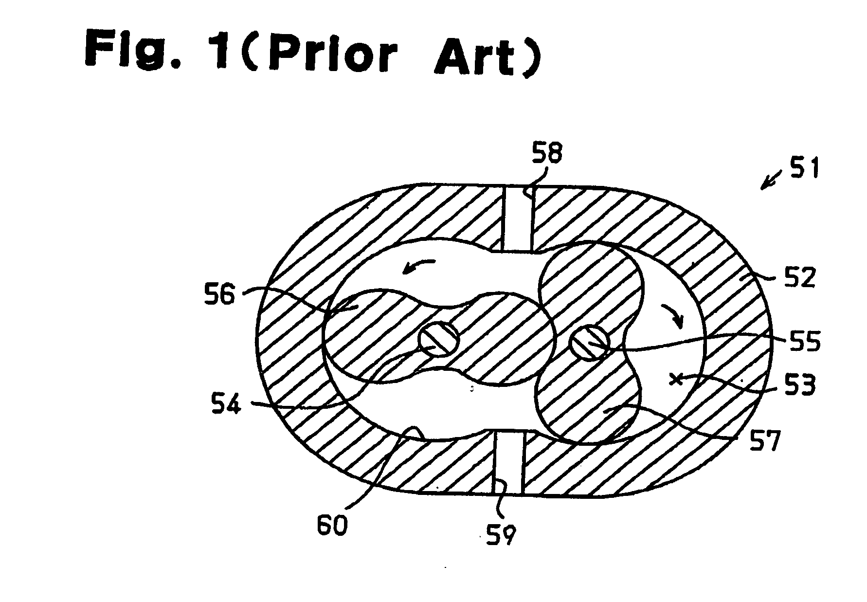
BACKGROUND OF THE INVENTION [0001] The present invention relates to a compressor, and more particularly, to a compressor for compressing fluid drawn into a pump chamber by rotating a rotor and discharging the fluid out of the pump chamber through a discharge port. [0002] A compressor that compresses fluid, or a fluid compressor, may be used in, for example, a fuel cell system. A fuel cell uses hydrogen gas and an oxidizer gas to generate electric power. The fuel cell produces water when generating power. To discharge the water out of the fuel cell, more hydrogen gas and oxidizer gas than the amount of hydrogen gas and oxidizer gas consumed to generate power must be supplied to the fuel cell. Further, the fuel cell discharges hydrogen gas (i.e., hydrogen off gas), which includes hydrogen gas that was not subject to reaction. The discharge of such hydrogen gas lowers fuel efficiency. To improve fuel efficiency, a typical compressor positively circulates the hydrogen off gas and mixes ...

Claims


Application Information

Patent Timeline
Patent Type & Authority Applications(United States)
IPC IPC(8): F04C18/18F04C29/00
CPCF04C29/0092F04C2240/102F04C2210/24
Inventor SHIROMARU, KATSUTOSHIKAWAMURA, KOJIKATO, HIROAKIFUJII, TOSHIRO
Owner TOYOTA IND CORP
Learn More