Reduction of power consumption and interference power in transmit power control system

a power control system and power consumption technology, applied in power management, transmission monitoring, sustainable buildings, etc., to achieve the effect of reducing power consumption and interference power

Inactive Publication Date: 2005-05-26
NEC CORP
View PDF10 Cites 2 Cited by
  • Summary
  • Abstract
  • Description
  • Claims
  • Application Information

AI Technical Summary

Benefits of technology

[0007] It is an object of the present invention to provide a transmit power control system, mobile station and transmit power control method capable of reducing power consumption and interference power even in a drastically varying propagation environment.
[0009] This makes it possible to set an outer loop initial value at a high degree of accuracy even in a drastically varying propagation environment and thereby reduce power consumption and reduce interference power in the system.

Problems solved by technology

However, the transmit power control system according to Patent Document 1 has a fixed outer loop initial value, and therefore the initial transmit power is higher than an optimum value, involving a problem in aspects of power consumption and interference with user data of other users.

Method used


Image

  • Reduction of power consumption and interference power in transmit power control system
  • Reduction of power consumption and interference power in transmit power control system
  • Reduction of power consumption and interference power in transmit power control system

Examples


1st embodiment

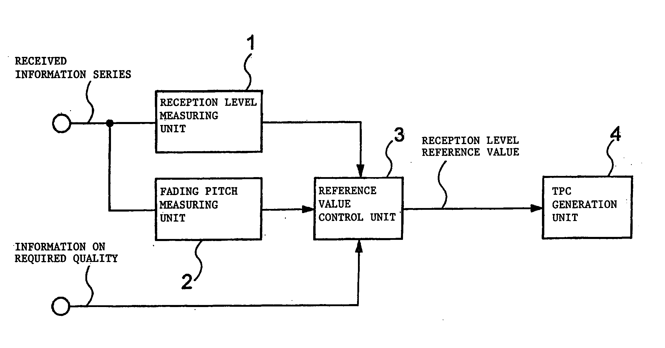
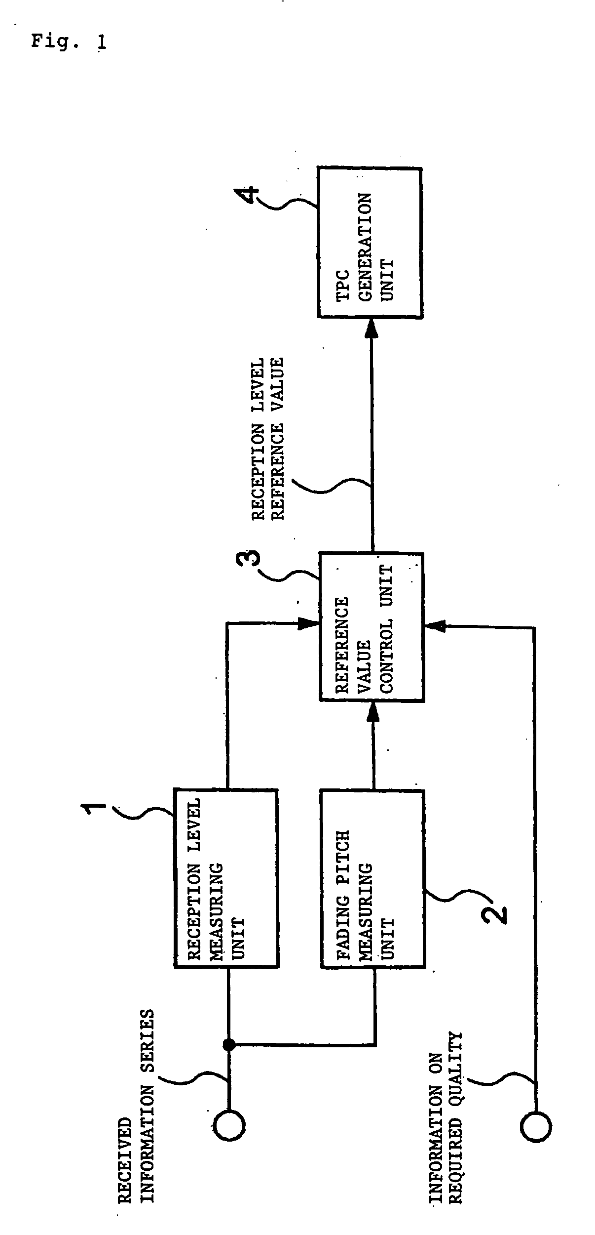
[0014]FIG. 1 shows the structure of a transmit power control system according to a first embodiment of the present invention. FIG. 1 shows the structure of a mobile station in a transmit power control system of this embodiment.

[0015] According to FIG. 1, the mobile station in the transmit power control system according to this embodiment is provided with a reception level measuring unit 1, a fading pitch measuring unit 2, a reference value control unit 3 and a TPC (Transmit Power Control information) generation unit 4. The reception level measuring unit 1 and reference value control unit 3 are connected to each other and the fading pitch measuring unit 2 and reference value control unit 3 are connected to each other. Furthermore, the reference value control unit 3 and TPC generation unit 4 are connected to each other.

[0016] The mobile station shown in FIG. 1 receives pilot signals (received information series) sent all the time from a base station which is not shown. Based on the ...

2nd embodiment

[0024] A second embodiment of the present invention differs from the first embodiment in that the reception level is weighted not at a fading pitch but according to information on the cell in which the mobile station is located (e.g., topographic information such as urban and rural areas, etc.).

[0025]FIG. 3 shows the structure of a transmit power control system according to the second embodiment of the present invention. In FIG. 3, the same components as those in the first embodiment (see FIG. 1) are assigned the same reference numerals and explanations thereof will be omitted.

[0026] According to FIG. 3, the only difference from FIG. 1 is that the fading pitch measuring unit 2 is replaced by a cell information measuring unit 5.

[0027] That is, the cell information measuring unit 5 measures cell information included in pilot signals sent from the base station. A reference value control unit 3 assigns a weight to the reception level measured by the reception level measuring unit 1 a...


PUM


Abstract

In a transmit power control system according to the present invention, a reception level measuring unit measures a reception level based on pilot signals sent from a base station to a mobile station and a fading pitch measuring unit measures a fading pitch. A reference value control unit assigns a weight to the reception level with the fading pitch and sets an outer loop initial value of transmit power control based on the weighted reception level and information on required quality specified by the base station when an individual channel is set.

Description

BACKGROUND OF THE INVENTION [0001] 1. Field of the Invention [0002] The present invention relates to a transmit power control system, mobile station and transmit power control method, and more particularly, to those used in a mobile communication system based on a CDMA (Code Division Multiple Access) mode. [0003] 2. Description of the Related Art [0004] A transmit power control technology is indispensable for a mobile communication system based on a CDMA mode. A technology of dynamically changing a target value of transmit power control to keep communication quality constant is an outer loop. As a conventional transmit power control system, the technology disclosed in Japanese Patent Application Laid-Open No. 2000-196566 (hereinafter referred to as “Patent Document 1”) has a fixed initial value for an outer loop, and therefore a value including a certain degree of margin is set for the initial value assuming a drastically varying propagation environment. [0005] Furthermore, Japanese...

Claims


Application Information

Patent Timeline
Patent Type & Authority Applications(United States)
IPC IPC(8): H04B7/26H04B7/005
CPCH04W52/12Y02B60/50H04W52/50
Inventor WAKIZAKA, YOSHIKI
Owner NEC CORP
Why Eureka
Try Eureka