Anesthesia monitor, capacitance nanosensors and dynamic sensor sampling method

a nanosensor and sensor technology, applied in the field of nanostructured sensor systems, can solve the problems of high cost of apparatus, high cost of calibration, time and calibration gases, etc., and achieve the effects of saving setup time, avoiding cost overruns, and avoiding over-runs

Inactive Publication Date: 2008-01-24
NANOMIX
View PDF11 Cites 90 Cited by
  • Summary
  • Abstract
  • Description
  • Claims
  • Application Information

AI Technical Summary

Benefits of technology

[0039] Anesthesia agent monitors based on nanoelectronic sensors having aspects of the invention, such as nanotube-based capacitance and transistor devices, provide a device to inexpensively identify and measure concentrations of anesthesia agents in patient breath, allow surgical procedures to be more cost-effective, save setup time and allow more cost-effective delivery of medical care in places and countries were limited funds for health care do not allow for monitoring level of anesthesia gases in surgical procedures and where the anesthesiologist must rely on the mechanical settings of the vaporizer, a risky situation for patient safety.
[0040] Exemplary embodiments of nanoelectronic sensors having aspects of the invention have a conductive (e.g., semiconducting) nanostructured element, the nanostructured element comprising a nanostructured material. The nanostructured material may include one or more nanotubes or the like (e.g., nanorods, nanowires; and / or nanoparticles). In certain embodiments, a nanostructured material may comprise a film, mat, array or network of nanotubes or the like. The nanostructured element may be configured to include a layer, coating or channel, and may be disposed adjacent a substrate or support structure. Nanostructured materials comprising a nanostructured element may be non-functionalized, or may functionalized to alter properties. In some embodiments, a nanoelectronic sensor may include a recognition material, layer or coating disposed in association with the nanostructured element, wherein the recognition material may be configured to influence the response of the sensor to an analyte of interest (e.g., increase sensitivity, response rate, or the like) and / or may be configured to influence the response of the sensor to the operating environment (e.g., increase selectivity, reduce interference or contamination, or the like).
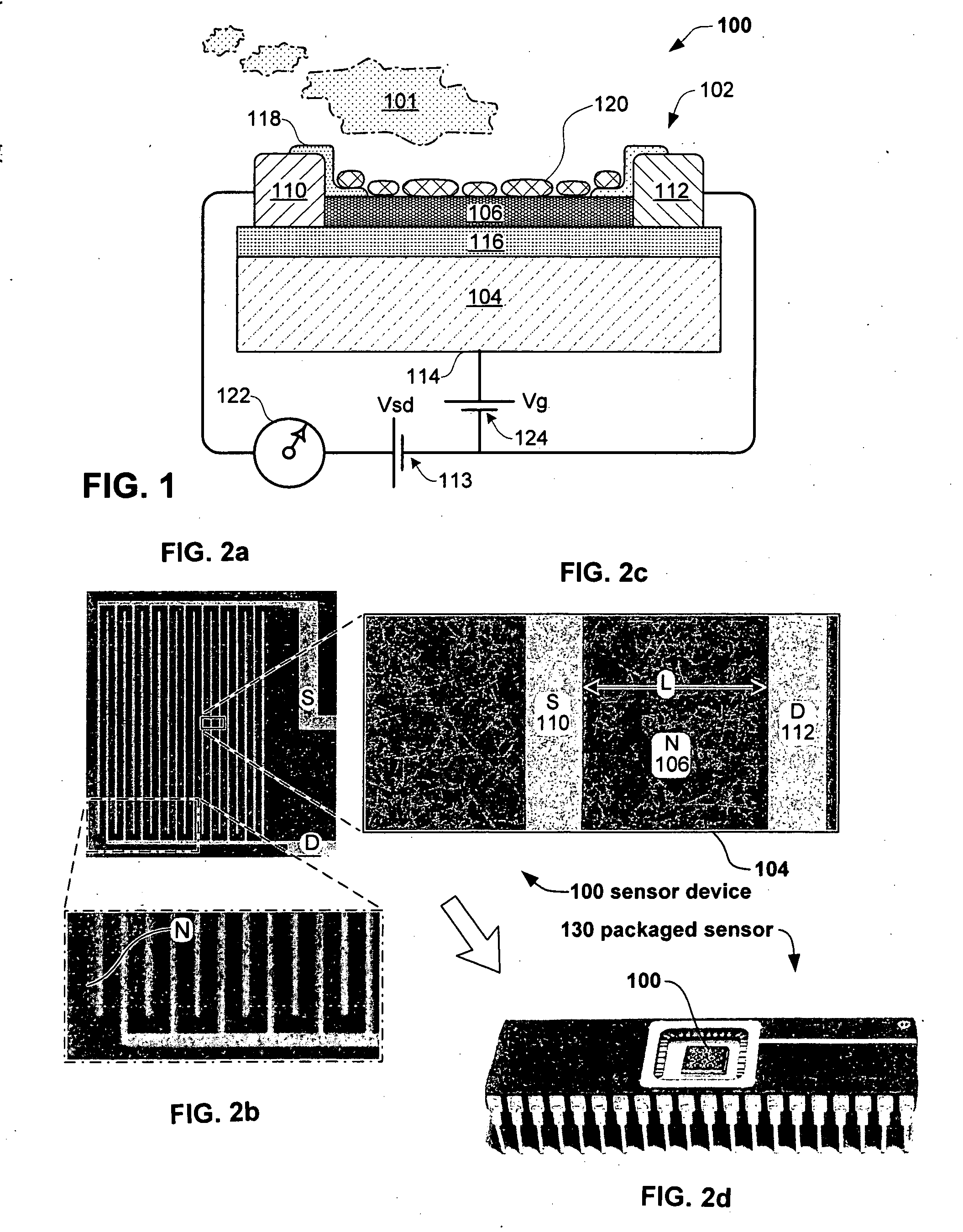
[0042] Nanoelectronic sensor embodiments provide a large sensing surface in a tiny, low-power package which can directly sample and selectively monitor anesthesia agent concentrations. A single sensor chip may include a plurality of sensors, capable of measuring multiple anesthetic agents, such as N2O, Isoflurane, sevoflurane and desflurane which are currently the most commonly used agents in the USA, as well as CO2 and other breath species. Much of the signal processing may be built into the sensor board, requiring only simple and inexpensive external instrumentation for display and data logging, so as to provide a fully calibrated, sterilized, packaged and disposable anesthesia gas sensor. The small size of the nanoelectronic sensors permit them to fit directly in an anesthesia system airway, so as to avoid cumbersome tubing, condenser, pump, and exhaust system currently required to perform sampling.
[0044] Alternative embodiments having aspects of the invention are configured for detection of analytes employing nanostructured sensor elements configured as one or more alternative types of electronic devices, such as capacitive sensors, resistive sensors, impedance sensors, field effect transistor sensors, and the like, or combinations thereof. Two or more such measurement strategies in a may be included in a sensor device so as to provide orthogonal measurements that increase accuracy and / or sensitivity. Alternative embodiments have functionalization groups or material associated with the nanostructured element so as to provide sensitive, selective analyte response.
[0055] One embodiment of a method having aspects of the invention comprises the steps of selectively exposing a sensor to a sample (e.g., delimiting sensor exposure by means of fluidic lumens and valves), and dynamically sampling a signal output from the sensor (e.g., delimiting signal to selected response ranges, time intervals and the like), so as to determine the presence or concentration of an analyte of interest by analysis of the dynamically sampled signal. Advantageously, the sensor may be exposed to a sample environment only intermittently without reducing the effective real-time monitoring of an analyte in the environment (e.g., the sensor exposure may be sequenced by an automatic fluidic sampling system). Furthermore, the physio-chemical impacts of the environment upon the sensor may be substantially reduced, without reducing the effective real-time monitoring of an analyte in the environment (e.g., sensor service life may be extended).

Problems solved by technology

The measurement apparatus typically costs over $5,000 (e.g., Datex-Ohmeda Div. of Instrumentarium Corp., Helsinki, Finland) and requires daily calibration, costly in human resources, time and calibration gases.
All together, the sampling and detection apparatus adds a bulky and cumbersome presence in the surgical suite.
However, None of these approaches offer the required selectivity for the simple field measurement envisioned herein.
The use of enflurane and halothane in clinical anesthesia has either disappeared or declined in the US, due mainly to their significant toxicities.
If anesthesia gas monitoring could be done using a no-maintenance low-cost disposable sensor instead of a high maintenance, high operation cost and expensive IR detectors, significant savings would result.
The high cost, complexity, weight and other limitations of this technology restrict the use of capnography to high value, controlled environments, such as surgical wards.
This limits the medical use of capnography.
Thus, lower cost, simplified and integratable devices for the monitoring of anesthesia agents will greatly improve patient care in places and countries were limited funds for health care do not allow for monitoring level of anesthesia gases in surgical procedures and where the anesthesiologist must rely on the mechanical settings of the vaporizer, a risky situation for patient safety.

Method used


Image

  • Anesthesia monitor, capacitance nanosensors and dynamic sensor sampling method
  • Anesthesia monitor, capacitance nanosensors and dynamic sensor sampling method
  • Anesthesia monitor, capacitance nanosensors and dynamic sensor sampling method

Examples


embodiment 50

[0128]FIG. 5 shows schematic architecture of a sensor device embodiment 50 having aspects of the invention for detection and measurement of analyte species, for example, by detection of electrochemical energy associated with the presence of an analyte. The device 50 comprises a sensor substrate 52 (e.g., comprising PET, polycarbonate, flexible polymers, or the like) having a reaction or sensor tip portion of its surface 60 on which an interconnecting carbon nanotube (CNT) network 54 is disposed. In the example of FIG. 5, a conductive trace or drain 55 electrically communicates with the network 54 (e.g., silver ink may be deposited on the substrate 12 so as to contact a portion of the network 54). Device 50 includes a well or container 57 holding buffer or fluid media 59 in which both sensor tip 60 and a gate electrode 58 are immersed. In certain embodiments, gate electrode 58 may include a reference electrode, such as a Ag / AgCl reference electrode, saturated calomel electrode, or th...

embodiment 10

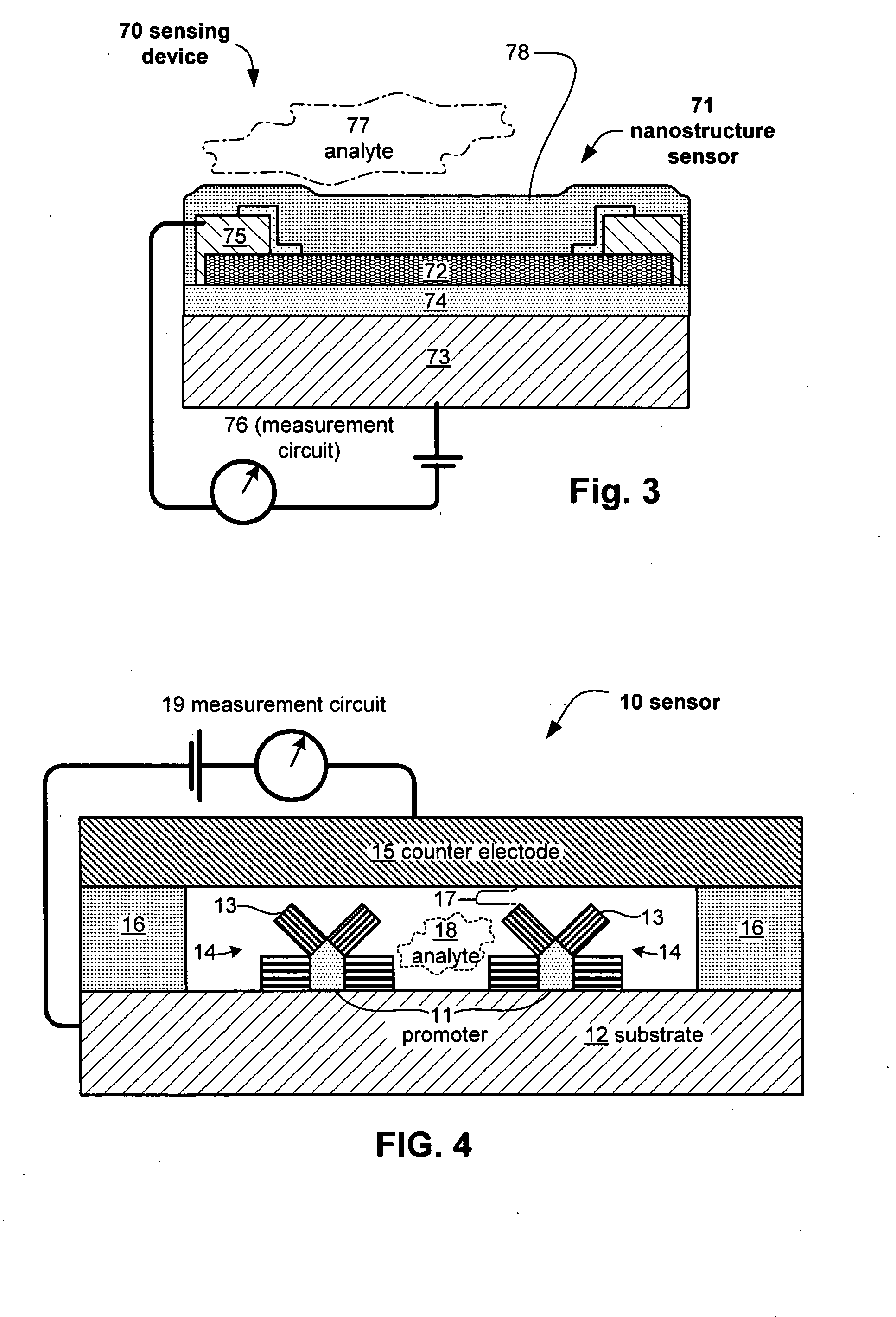
[0201]FIG. 16 is a plan view, cross-sectional view, and equivalent circuit diagram of an exemplary capacitive nanosensor embodiment 10 having aspects of the invention, comprising a bi-layer architecture including a substrate 11 (e.g., PET) and a conductive base or plate 12 (e.g., metal such as Au, graphite, and the like). A dielectric layer 13 (e.g., a polymer, SiO2, and the like, or combinations thereof is interposed between base plate 12 and a nanostructured element 14 (such as one or more CNT or a CNT network). Nanostructured element 14 is capacitively coupled to conductive base 12 in that base 12 is space apart from element 14 to form a pair of capacitive plates. Digitated top lead 15 is shown contacting CNT element 14 to permit electrical communication with measurement circuitry (not shown). Preferably, top leads 15 are applied in such a manner as to prevent contact with base plate 12, so as to avoid a current path between a capacitive plate pair 12, 14, as shown in equivalent ...

embodiment 20

[0202]FIG. 17 is a plan view, cross-sectional view, and equivalent circuit diagram of an alternative exemplary capacitive nanosensor embodiment 20 having aspects of the invention, comprising off-set capacitor elements in series, including a substrate 21 (e.g., PET) and an offset pair of conductive leads 22, 23 (e.g., metal such as Au, graphite, and the like), preferably disposed side-by-side adjacent substrate 21, separated by a selected gap. Dielectric layer 24 (e.g., a polymer, SiO2, and the like, or combinations thereof covers active regions of leads 22, 23 and in turn supports CNT element 25, such as a carbon nanotube network. Advantageously, CNT element 25 forms a common capacitive plate electrode opposing both leads 22 and 23 (capacitively coupled), as shown in equivalent circuit 26.


PUM

PropertyMeasurementUnit
electrical propertyaaaaaaaaaa
conductiveaaaaaaaaaa
dielectricaaaaaaaaaa

Abstract

Embodiments of nanoelectronic sensors are described, including sensors for detecting analytes such as anesthesia gases, CO2 and the like in human breath. An integrated monitor system and disposable sensor unit is described which permits a number of different anesthetic agents to be identified and monitored, as well as concurrent monitoring of other breath species, such as CO2. The sensor unit may be configured to be compact, light weight, and inexpensive. Wireless embodiments provide such enhancements as remote monitoring. A simulator system for modeling the contents and conditions of human inhalation and exhalation with a selected mixture of a treatment agent is also described, particularly suited to the testing of sensors to be used in airway sampling.

Description

CROSS-REFERENCE TO RELATED APPLICATION [0001] This application claims priority pursuant to 35 USC. § 119(e) to the following US Provisional Applications, each of which applications are incorporated by reference: [0002] No. 60 / 730,905 filed Oct. 27, 2005, entitled “Nanoelectronic Sensors And Analyzer System For Monitoring Anesthesia Agents And Carbon Dioxide In Breath”[0003] No. 60 / 850,217 filed Oct. 6, 2006, entitled “Electrochemical nanosensors for biomolecule detection”; [0004] No. 60 / 773,138 filed Feb. 13, 2006 entitled “Nanoelectronic Capacitance Sensors For Monitoring Analytes”; [0005] No. 60 / 748,834 filed Dec. 9, 2005 entitled “Nanoelectronic Sensors Having Substrates With Pre-Patterned Electrodes, And Environmental Ammonia Control System”. [0006] This application is a continuation-in-part of and claims priority to U.S. patent application Ser. No. 11 / 488,456 filed Jul. 18, 2006 (published 2006-______) entitled “Improved Carbon Dioxide Nanosensor, And Respiratory CO2 Monitors” ...

Claims


Application Information

Patent Timeline
Patent Type & Authority Applications(United States)
IPC IPC(8): A61B5/08G01N31/22
CPCA61B5/0833A61B5/097B82Y30/00A61B5/6819A61B2562/0285A61B5/4821
Inventor GABRIEL, JEAN-CHRISTOPHE P.JOSHI, VIKRAMPASSMORE, JOHN LORENSKARUPO, SERGEISTAR, ALEXANDERVALCKE, CHRISTIAN
Owner NANOMIX
Why Eureka
Try Eureka