Apparatus and methods for delivery of transcranial magnetic stimulation

a transcranial magnetic stimulation and apparatus technology, applied in the field of transcranial magnetic stimulation, can solve the problems of unsafe hand-held delivery, and inability to identify proper orientation, so as to reduce the electric field on the patient, reduce the electric field, and reduce the effect of power

Active Publication Date: 2005-05-26
BOARD OF RGT THE UNIV OF TEXAS SYST
View PDF34 Cites 183 Cited by
  • Summary
  • Abstract
  • Description
  • Claims
  • Application Information

AI Technical Summary

Benefits of technology

[0015] The present invention enhances the precision and ease with which TMS may be used for the diagnosis and treatment of neurological and psychiatric disorders and for neuroscience research. In certain embodiments, these benefits may be accomplished via use of specifically shaped TMS stimulators having certain properties. In certain embodiments, a robot, such as a neurosurgical robot, may be used to deliver TMS. The present invention also includes algorithms for treatment planning and treatment delivery, including: algorithms for rapidly modeling the 3-D electric field created in the brain by a TMS coil at any external location; cortical surface modeling (extraction and visualization); scalar product (electric-field vector times cortical-surface vector) computation and visualization; and merging of functional images, structural images and treatment-planning models (surfaces & fields).
[0017] Additionally, inventive methods enhance the precision and ease with which TMS may be used for neuroscience research and for the diagnosis and treatment of neurological and psychiatric disorders.
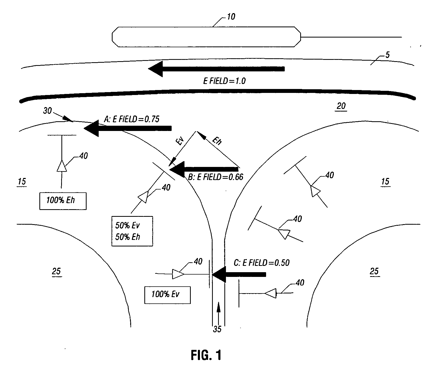
[0022] In FIG. 1, the TMS coil 10 is positioned and oriented to create an induced E-field that is perpendicular to the brain cortical surface (and parallel to the vertical neurons) in the sulcus (B), but parallel to the cortical surface (and perpendicular to the vertical neurons) at the crown of the gyrus (A). The magnitude of the E field is weaker at C than at A, because the distance from the surface of the TMS coil 10 is greater at C than at A. Relative to the orientation of the vertical neurons forming the cortical columns the E field can be decomposed into vertical (Ev) and horizontal (Eh) components, which are parallel to the vertical neurons and horizontal fibers, respectively. By Principal (2), activation at any cortical site is a function of Ev with negligible Eh effect. Thus, E has no effect (no Ev component) where E is perpendicular to the column (A); intermediate effects for intermediate relative orientations (B); and maximal effect where E is parallel to the column (C).
[0031] In an example embodiment, TMS delivery may be effected by means of a robotic arm. Using a robotic arm to move, aim and hold the TMS provides many benefits. First, a robotic arm allows the TMS coil to be placed and oriented with accuracy and precision of −1 mm (location) and—1° (orientation), far exceeding hand-holding. This degree of accuracy and precision is crucial for implementing a high-precision aiming algorithm. Second, a robotic arm allows the TMS to be positioned automatically, i.e., under computer control. Third, a robotic arm allows the TMS to be positioned rapidly, saving time for the patient, experimentor or clinician. Fourth, a robotic arm can accurately re-establish its position on sequential days, which is needed for experiments and treatments applied over a series of sessions. Fifth, a robotic arm allows the TMS to be moved rapidly from one position to another, allowing treatment of more than one location in a single session. Sixth, a robotic arm allows the TMS to be held immobile for long periods of time, which a person cannot practically or comfortably achieve. Seventh, a robotic arm allows TMS to be delivered during PET imaging, without exposing a human holder to radiation.
[0033] Coils may be designed in accordance with the teachings of the present invention to incorporate one or more of the following characteristics which aid in the delivery of transcranial magnetic stimulation. In certain embodiments, a coil may be designed to provide for minimum inductance for a given set of field constraints. Further, a coil may be designed to dissipate a minimum amount of power for a given set of field constraints. Similarly, a coil may be designed to provide for minimum inductance and minimum dissipation for a given set of field constraints. In certain embodiments, a coil may be designed with negative turns to reduce the electric field on a patient. Such negative turns also may be provided in a separate layer to similarly reduce electric field on the patient.

Problems solved by technology

Further, when using the 10 / 20 system, there has been no strategy enunciated for determining proper orientation of the coil.
For both of these applications, hand-held TMS delivery is inappropriate, for at least three reasons.
First, hand-held delivery is unsafe, unnecessarily exposing the experimentor to the radiation used for imaging.
Second, hand-held delivery is positionally unstable, degrading image quality by small movements of the holder.
Third, hand-held delivery is intrinsically inaccurate and imprecise.
Further, current coil designs for delivery of TMS have been mainly intuitive and somewhat crude.
However, such design methods have not been applied to the design of magnetic stimulation coils.
However, none of these provide an extremely focused field penetration.
However, these designs are largely limited by intuition.
Thus, fundamental limitations on the utility of TMS for research and treatment include a lack of methods for precise, automated aiming (positioning and orienting) and safe, rigid (i.e., non-human) holding of the TMS stimulator, as well as the poor suitability of present coils for TMS.

Method used


Image

  • Apparatus and methods for delivery of transcranial magnetic stimulation
  • Apparatus and methods for delivery of transcranial magnetic stimulation
  • Apparatus and methods for delivery of transcranial magnetic stimulation

Examples


experiment 1

[0076] By Principle 3, maintaining the E-field at a field orientation but varying the strength of the field should vary the degree of TMS-induced neuronal activity. Eight normal volunteers were imaged by PET while undergoing 3-Hz TMS stimulations across a range of intensities. Stimulation was applied to the Supplementary Motor Area on the medial surface of the right frontal lobe of the cerebral hemisphere. The E-field was oriented perpendicular to the cortical surface, which was also perpendicular to the mid-sagittal plane and exactly 90° rotated from the orientation required by the “B-nose” principle, described above. This stimulation produced strong activation on the medial-bank cortical surface at the location in which the E-field was most perpendicular to the cortical surface, as predicted by Principles 2 and 3. Response magnitude was highly correlated with TMS E-field strength, as predicted by Principle 3.

experiment 2

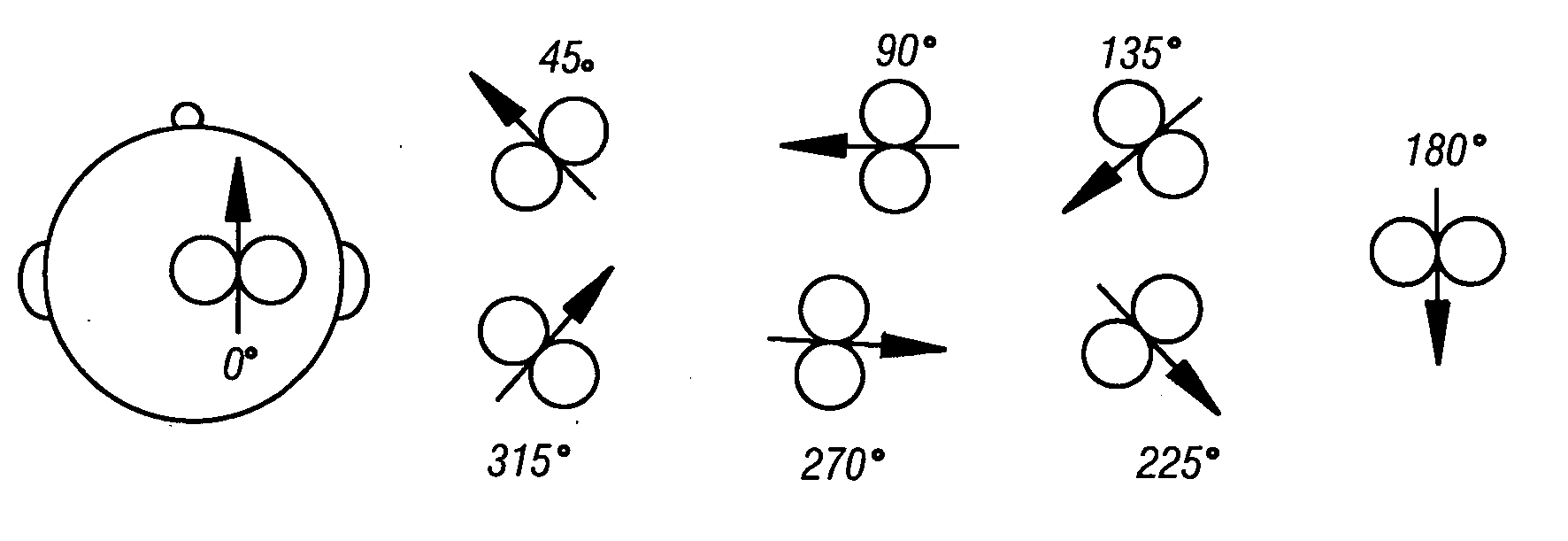
[0077] By Principles 2 and 3, varying the orientation of the TMS E-field relative to the cerebral cortical surface should modulate response magnitude, with the greatest response being observed when the E-field is perpendicular to the cortical surface. Twelve normal volunteers were imaged by PET while undergoing 3 Hz TMS at fixed intensity but varying orientation: 0°, 30°, 60° and 90° relative to the cortical surface. Stimulation was applied to the foot area of primary motor cortex. As predicted by Principles 2 and 3, the response was located on the bank of the central sulcus, rather than on the gyral crown. Also as predicted by the same principles, response magnitude was highly correlated with TMS E-field orientation, with the greatest response occurring when the field was at 90° to the cortical surface, as shown in FIG. 6.

[0078] To take advantage of the aiming principles set forth herein, it is desirable to use a TMS stimulator having properties which allow it to generate an E fie...


PUM


Abstract

Disclosed are apparatus and methods for delivery of transcranial magnetic stimulation. The apparatus includes a TMS coil which when energized generates an electric field substantially parallel to a long axis of the coil and substantially normal to a surface of the coil. Furthermore disclosed an apparatus for delivery of TMS in which a coil is adapted to a robotic member for computer-aided control and delivery. Further disclosed are methods of TMS planning and delivery in which subject images are utilized to plan, position and orient the TMS coil for precise delivery. Disclosed also are TMS coils having unique designs to better focus and direct magnetic stimulation.

Description

[0001] This application claims priority to the U.S. Provisional Application No. 60 / 288,670 filed on May 4, 2001 in the name Peter Fox and Jack Lancaster entitled APPARATUS AND METHODS FOR DELIVERY OF TRANSCRANIAL MAGNETIC STIMULATION.[0002] This invention was made with government support under contract number 5R01MH60246-02. The government has certain rights in this invention.BACKGROUND OF THE INVENTION [0003] 1. Field of the Invention [0004] The present invention is directed to apparatus and methods particularly suitable for precise aiming and delivery of magnetic stimulation, and more specifically, transcranial magnetic stimulation. [0005] 2. Description of the Related Art [0006] Transcranial magnetic stimulation (“TMS”) is a means of repetitively stimulating the human brain through an intact scalp and skull, i.e., non-invasively. TMS is delivered by passing a brief (200 microsecond), strong (10,000 volts, 6,000 amps) electrical current through a coil of wire (a TMS stimulator) pl...

Claims


Application Information

Patent Timeline
Patent Type & Authority Applications(United States)
IPC IPC(8): A61N2/02A61N2/04
CPCA61N2/02A61N2/006A61B34/32A61B2034/305A61B34/37A61B34/10A61B2090/067A61B2034/2059
Inventor FOX, PETERLANCASTER, JACK
Owner BOARD OF RGT THE UNIV OF TEXAS SYST
Why Eureka
Try Eureka