Apparatus for controlling a hydraulic circuit for clutches

a technology of hydraulic circuit and clutch, which is applied in the direction of mechanical apparatus, couplings, braking systems, etc., can solve the problems of raising relevant production costs, affecting the construction simplicity of the device and its robustness, and the relative difficulty of adjusting the idle stroke of the control lever, etc., to achieve greater compactness, reduce the effect of overall dimensions and reduced labor intensity

Inactive Publication Date: 2005-06-02
FORMULA
View PDF7 Cites 16 Cited by
  • Summary
  • Abstract
  • Description
  • Claims
  • Application Information

AI Technical Summary

Benefits of technology

[0007] Among the advantages of the present invention there is the fact that it is possible to adjust the idle stroke for the operation of the clutch's hydraulic circuit with greatest ease; that the controlled circuit maintains its original characteristics; that no protruding parts are provided likely to be damaged or be a danger for the driver of the vehicle being equipped with the apparatus; that the apparatus has extremely limited overall dimensions and, therefore, gives the handlebar a greater compactness; that a more attractive appearance is conferred to the handlebar; that the apparatus keeps its characteristics unchanged also after a prolonged service life.

Problems solved by technology

In the motorcycles provided with a traditional apparatus of this type, a drawback is due to the relative difficulty of adjusting the idle stroke of the control lever.
This approach is however very complex structurally, and affects negatively the constructional simplicity of the device and its robustness upon use, besides raising the relevant production cost thereof.

Method used


Image

  • Apparatus for controlling a hydraulic circuit for clutches
  • Apparatus for controlling a hydraulic circuit for clutches
  • Apparatus for controlling a hydraulic circuit for clutches

Examples


Embodiment Construction

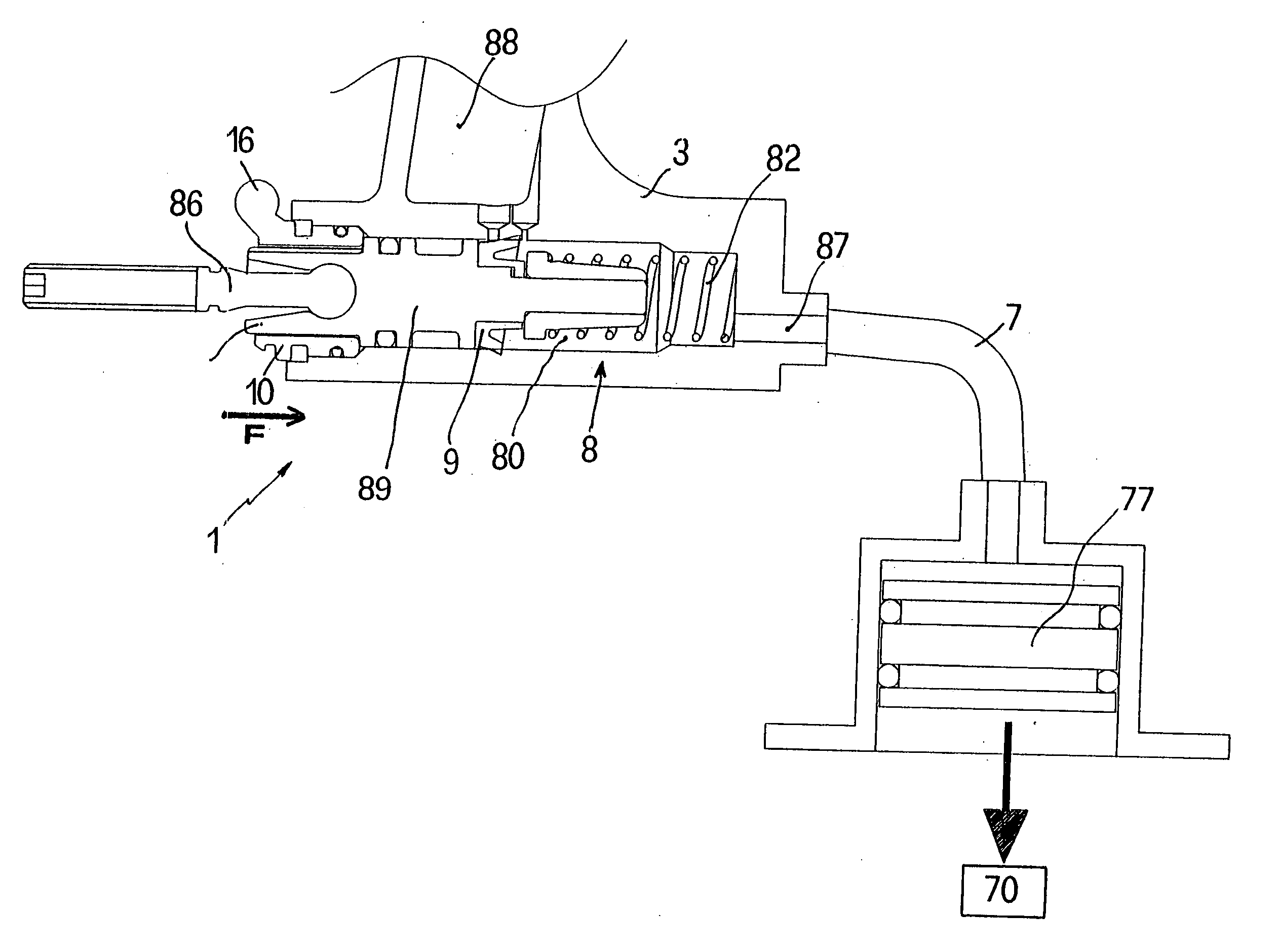
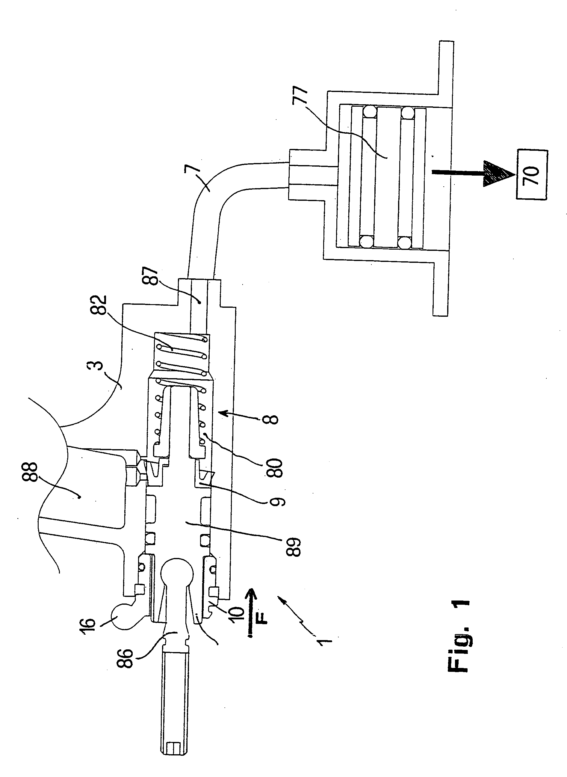
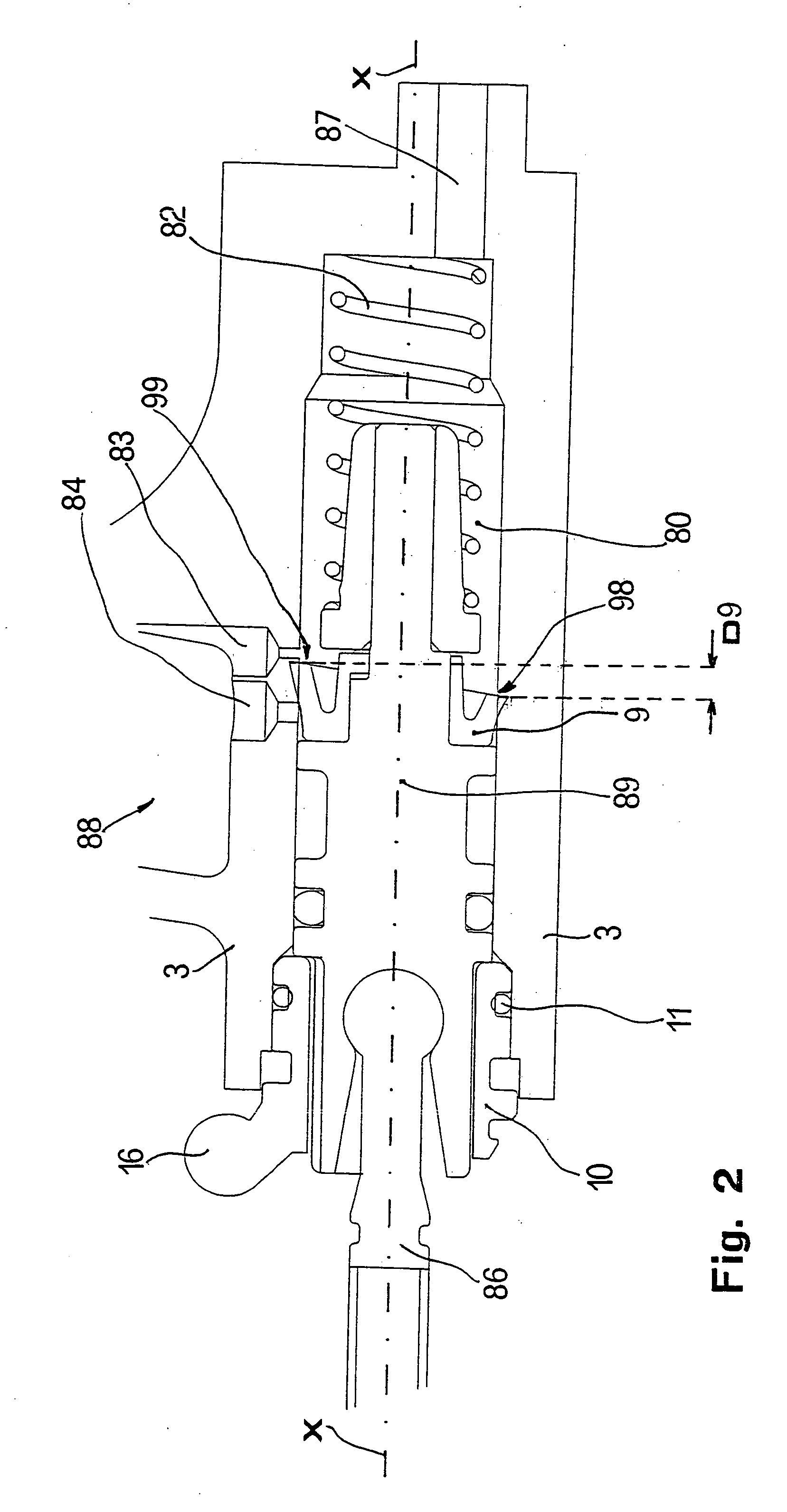
[0012] With reference to the example shown in the attached figures, an apparatus 1 according to the present invention can be associated with a portion of a motorcycle or the like, such as a handlebar, for example, by means of suitable fixing means (not shown). The present apparatus comprises a body 3 (shown only partially) inside which a cavity 88 is formed defining the reservoir for the fluid of the hydraulic circuit. The said reservoir 88 results positioned between the handlebar, to which the body 3 is fixed, and a lever for operating the pump acting on the hydraulic circuit of the clutch. The clutch-operating lever (not shown) results linked with a connecting rod 86 having spherical head, as represented on the left side of the attached figures.

[0013] Shown in FIG. 1 is a conduit 7 making part of the hydraulic circuit and connecting the apparatus 1 to the piston 77 which acts upon the clutch disks, the latter being schematically represented by the block 70 in FIG. 1.

[0014] The c...


PUM


Abstract

Apparatus for controlling a hydraulic circuit to be used for operating hydraulic clutches with a pump (8) connected with a relevant reservoir (88) for the fluid of the hydraulic circuit and comprising a piston (89) sliding within a relevant chamber (80) provided with one or more ports (83, 84) for connection to said reservoir (88), the said piston being so shaped as to close/open the said ports (83, 84) upon its stroke along said chamber (80), apparatus being characterized in that the idle stroke of the piston (89) within said chamber (80) is adjustable through a rotation of the same piston (89) about its longitudinal axis.

Description

[0001] The present invention relates to an apparatus for controlling a hydraulic circuit for a clutch of motor vehicles, especially of motorcycles and the like. BACKGROUND OF THE INVENTION [0002] It is known that the action to be exerted on the pack of the clutch diks is made easier by means of a hydraulic circuit which comprises a pump and a piston acting on the disks' pack. In the motorcycles, for example, a lever is provided for operating said pump whose activation determines the displacement of the piston. [0003] In the motorcycles provided with a traditional apparatus of this type, a drawback is due to the relative difficulty of adjusting the idle stroke of the control lever. In fact, in the existing devices, the lever is connected to a piston sliding into a respective chamber exhibited by the pump and, in order to adjust the idle stroke of the lever it is currently necessary to move axially the piston with respect to the chamber inside which it slides. This approach is however...

Claims


Application Information

Patent Timeline
Patent Type & Authority Applications(United States)
IPC IPC(8): B62K23/06F16D23/12F16D25/08F16D25/12
CPCB62K23/06F16D23/12F16D2025/081F16D25/126F16D25/088F16D25/08
Inventor BECOCCI, ANDREALAGHI, SAMUELE
Owner FORMULA
Why Eureka
Try Eureka