Plant and Method for Thermally Conditioning Plastic Items

a technology of thermal conditioning and plastic items, applied in the field of plants and a method for thermal conditioning plastic items, can solve the problem that plants must have limited dimensions

Inactive Publication Date: 2007-09-27
SIPA SOCIETA INDUSTRIALIZZAZIONE PROGETTAZIONE E AUTOMAZIONE SPA
View PDF17 Cites 17 Cited by
  • Summary
  • Abstract
  • Description
  • Claims
  • Application Information

AI Technical Summary

Problems solved by technology

Furthermore, this plant must have limited dimensions, especially in

Method used


Image

  • Plant and Method for Thermally Conditioning Plastic Items
  • Plant and Method for Thermally Conditioning Plastic Items
  • Plant and Method for Thermally Conditioning Plastic Items

Examples


example

[0055] To illustrate this invention better, an example is given with numerical data relating to a plant realized by the Applicant in accordance with the version of the invention shown in FIGS. 1-4.

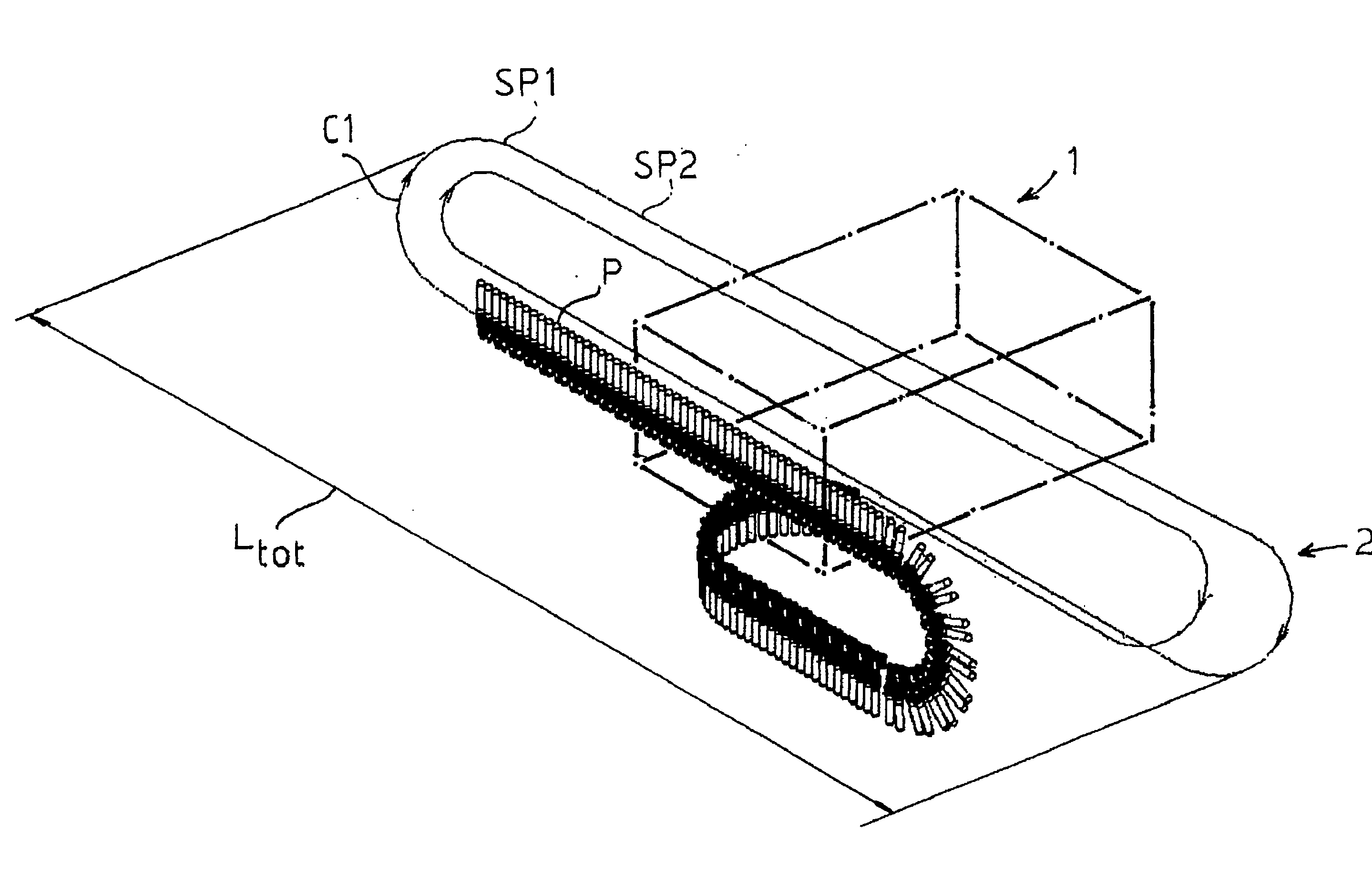
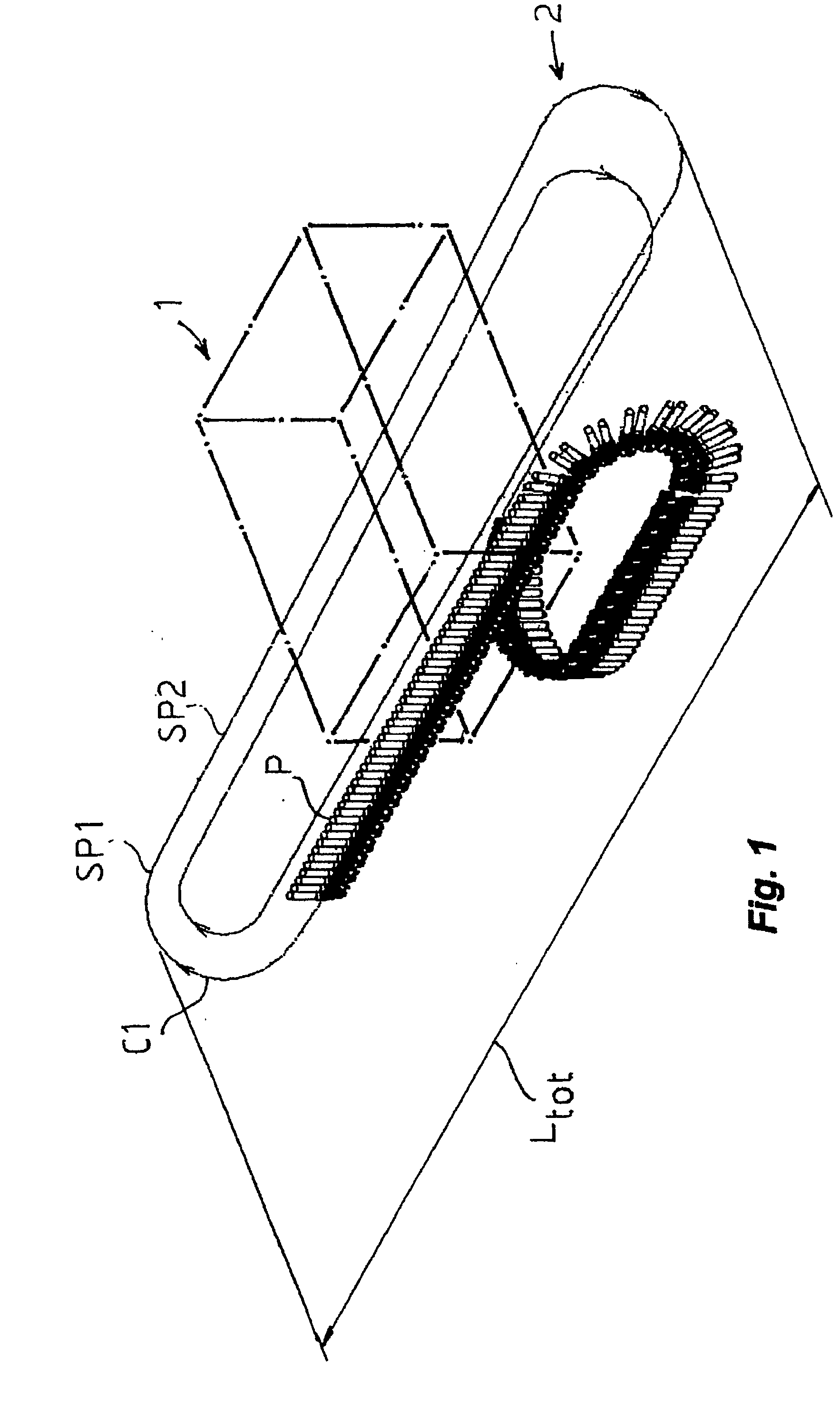
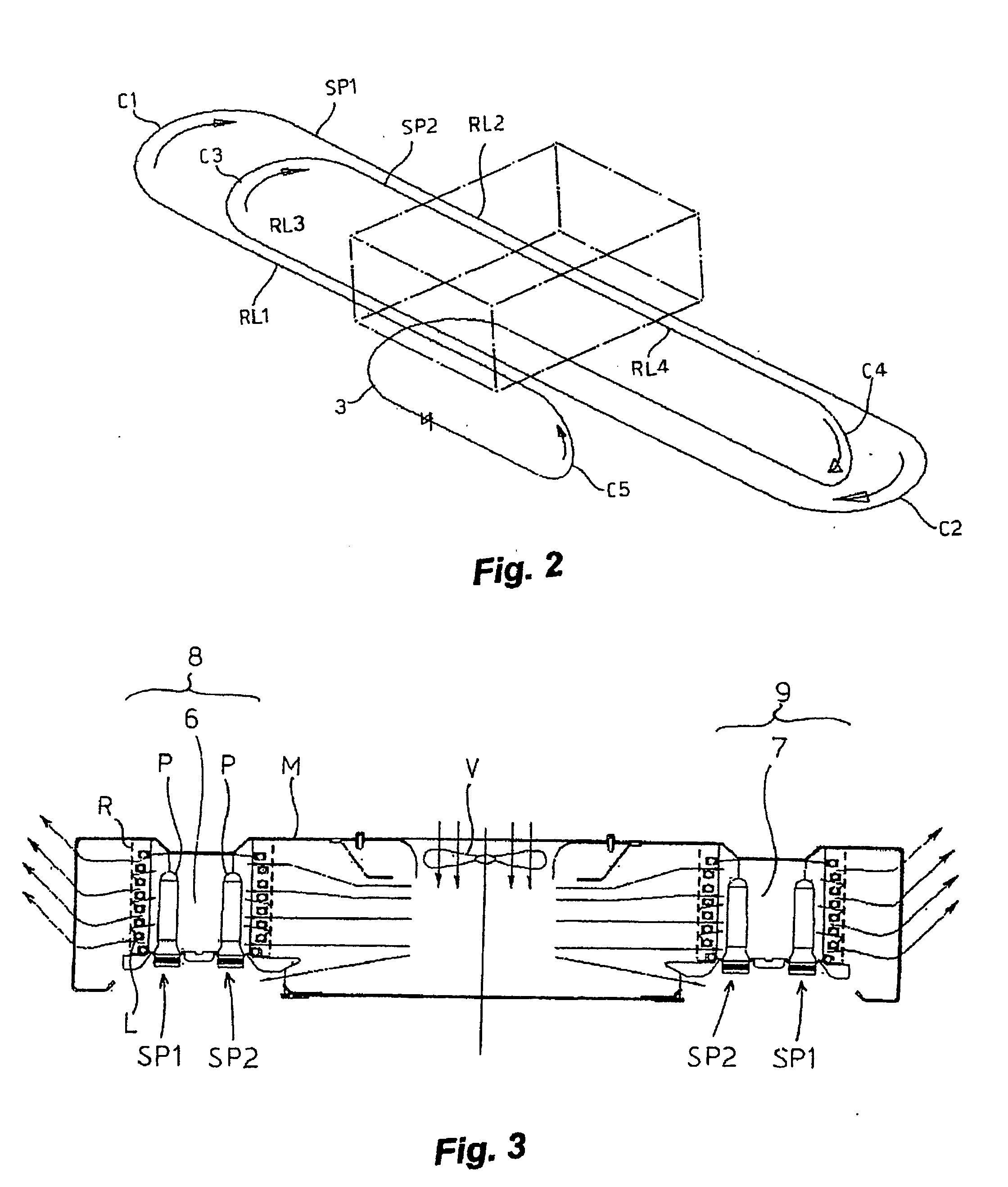
[0056] In said plant, the chain conveyor 2 forms a path with two spirals SP1, SP2 entering and exiting—as in FIG. 2—a single furnace 1 four times. The fact that the two chain spirals SP1, SP2 pass in two ducts 8, 9 reduces the thermal losses of the furnace, bringing its thermal efficiency—defined as the relation between the thermal energy required to bring a certain quantity of preforms from the starting temperature to the desired temperature, and the energy consumed by the furnace—indicatively, up to approximately 21-28%, against 15-20% for known types of infrared furnaces for example, a furnace of the type described in W00149075 with only one duct. The greater efficiency of the furnace made it possible to realize the total path of the preforms in front of the IR lamps approximately 0.7 ...


PUM

PropertyMeasurementUnit
Lengthaaaaaaaaaa
Dimensionaaaaaaaaaa

Abstract

The method for thermally conditioning preforms in accordance with the invention comprises the following steps:—Placing the preforms on a chain conveyor (2);—Conveying the preforms through a first thermal conditioning stage (1) and subjecting them to a first heating or cooling heat exchange;—Removing the preforms from the first thermal conditioning stage and holding them outside for a predetermined amount of time in order to redistribute the temperature inside the preforms;—Subjecting the preforms to at least a second heating or cooling heat exchange in a second thermal conditioning stage (1) or in the first thermal conditioning state. The invention also concerns the plants for heating or cooling preforms in accordance with the above method.

Description

TECHNICAL FIELD [0001] This invention relates to a plant and a method for thermally conditioning plastic items such as preforms used in blow moulding processes to form bottles, pots, or other containers. More particularly, the invention relates to heating or cooling stations for preforms to be blow moulded using the so-called cold cycle. BACKGROUND ART [0002] Today, the production of blow moulded containers in different shapes and sizes—for example plastic bottles, pots, or other items—using the so-called cold cycle involves injection, compression, or extrusion moulding preforms or parisons made of a suitable plastic—for example, PET—and, then, cooling and storing the workpiece before the blow moulding process. [0003] To use the injection or other type of press in the most efficient way possible, the preform cooling stage in the mould is kept to a minimum by transferring the preforms, as soon as possible, to specific external cooling stations, where cooling is completed. [0004] To a...

Claims


Application Information

Patent Timeline
IPC IPC(8): B29C49/64B29C35/08B29C35/16B29C45/72B29C49/06B29C49/42B29C49/68
CPCB29C35/08B29C35/16B29C45/7207B29C49/06B29K2105/253B29C49/6472B29C49/68B29C2035/0822B29K2067/00B29C49/4205B29C49/42085B29C2949/0715B29C49/6454B29C49/648B29C49/6418B29C49/6845
Inventor ZOPPAS, MATTEOARMELLIN, ALBERTO
Owner SIPA SOCIETA INDUSTRIALIZZAZIONE PROGETTAZIONE E AUTOMAZIONE SPA
Why Eureka
Try Eureka