Seat drive motor and power seat system

a drive motor and seat technology, applied in the direction of movable seats, gear housings, transportation and packaging, etc., can solve the disadvantage of increasing the weight short life of the gear housing, and difficulty in installing the rotation sensor in the interior of the gear housing at the time of assembling the motor, so as to increase the lifetime of the housing, reduce the size of the housing, and reduce the effect of the weight of the housing

Inactive Publication Date: 2005-06-02
DENSO CORP
View PDF2 Cites 23 Cited by
  • Summary
  • Abstract
  • Description
  • Claims
  • Application Information

AI Technical Summary

Benefits of technology

[0009] The present invention addresses the above disadvantages. Thus, it is an objective of the present invention to provide a seat drive motor, which permits an increase in a lifetime of a housing of the seat drive motor. It is another objective of the present invention to provide a power seat system having such a seat drive motor. It is a further objective of the present invention to provide a seat drive motor, which permits a reduction in a size of a housing of the seat drive motor, a reduction in a weight of the housing and a reduction in material costs of the gear housing. It is another objective of the present invention to provide a power seat system having such a seat drive motor.

Problems solved by technology

When the power seat system has the above structure, in which the rotation sensor for measuring the rpm of the worm wheel is provided in an interior of the gear housing of the motor, it is difficult to install the rotation sensor in the interior of the gear housing at the time of assembling the motor.
This causes a short lifetime of the gear housing.
When the wall thickness of the gear housing is increased to reinforce the gear housing, a weight of the gear housing is disadvantageously increased, and a size of the gear housing is also disadvantageously increased.
Also, this results in an increase in material costs of the gear housing.

Method used


Image

  • Seat drive motor and power seat system
  • Seat drive motor and power seat system
  • Seat drive motor and power seat system

Examples


Embodiment Construction

[0034] An embodiment of the present invention will be described with reference to the accompanying drawings. It should be understood that the following components and arrangement thereof are not intended to limit the present invention and can be modified without departing from the scope of the present invention.

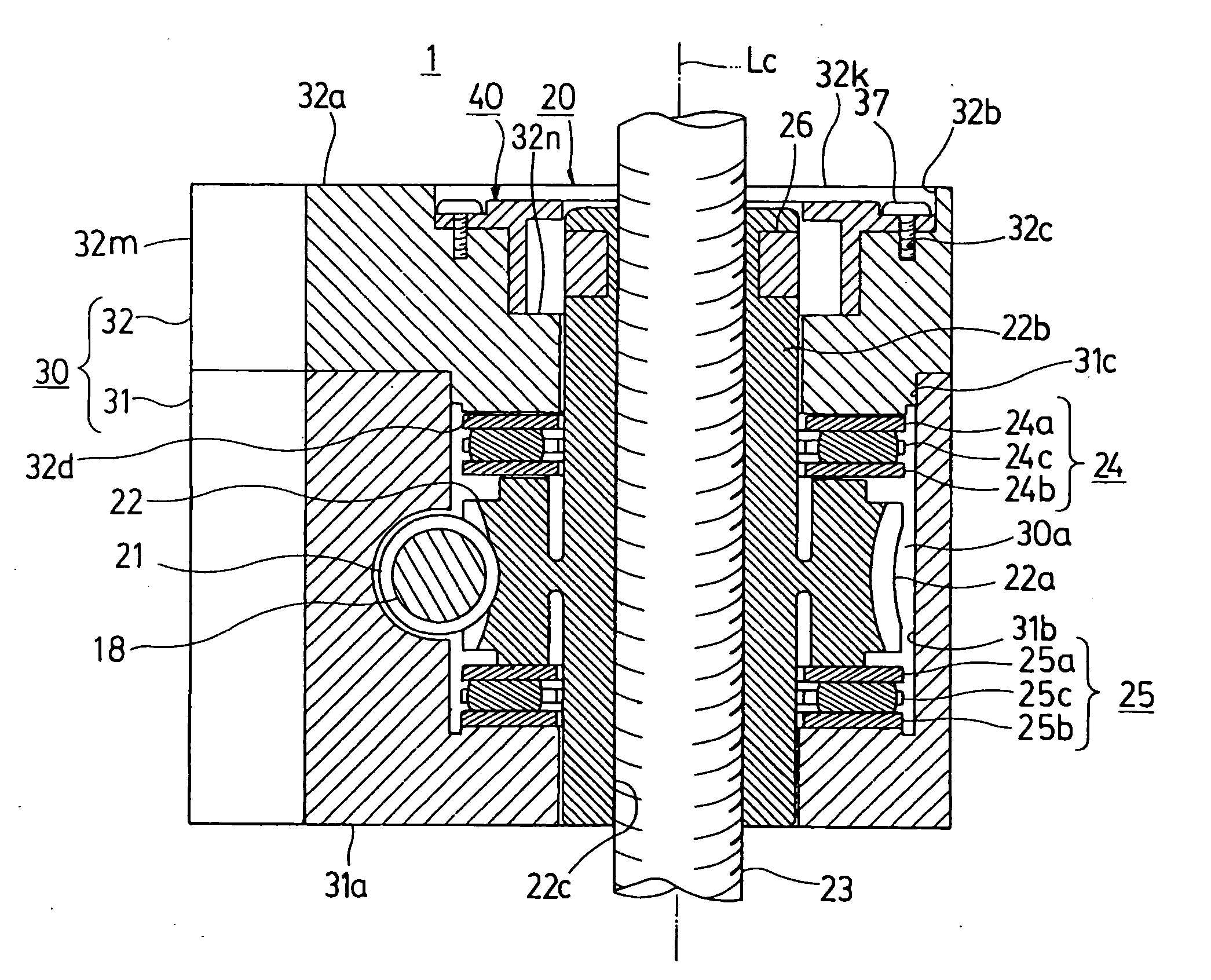
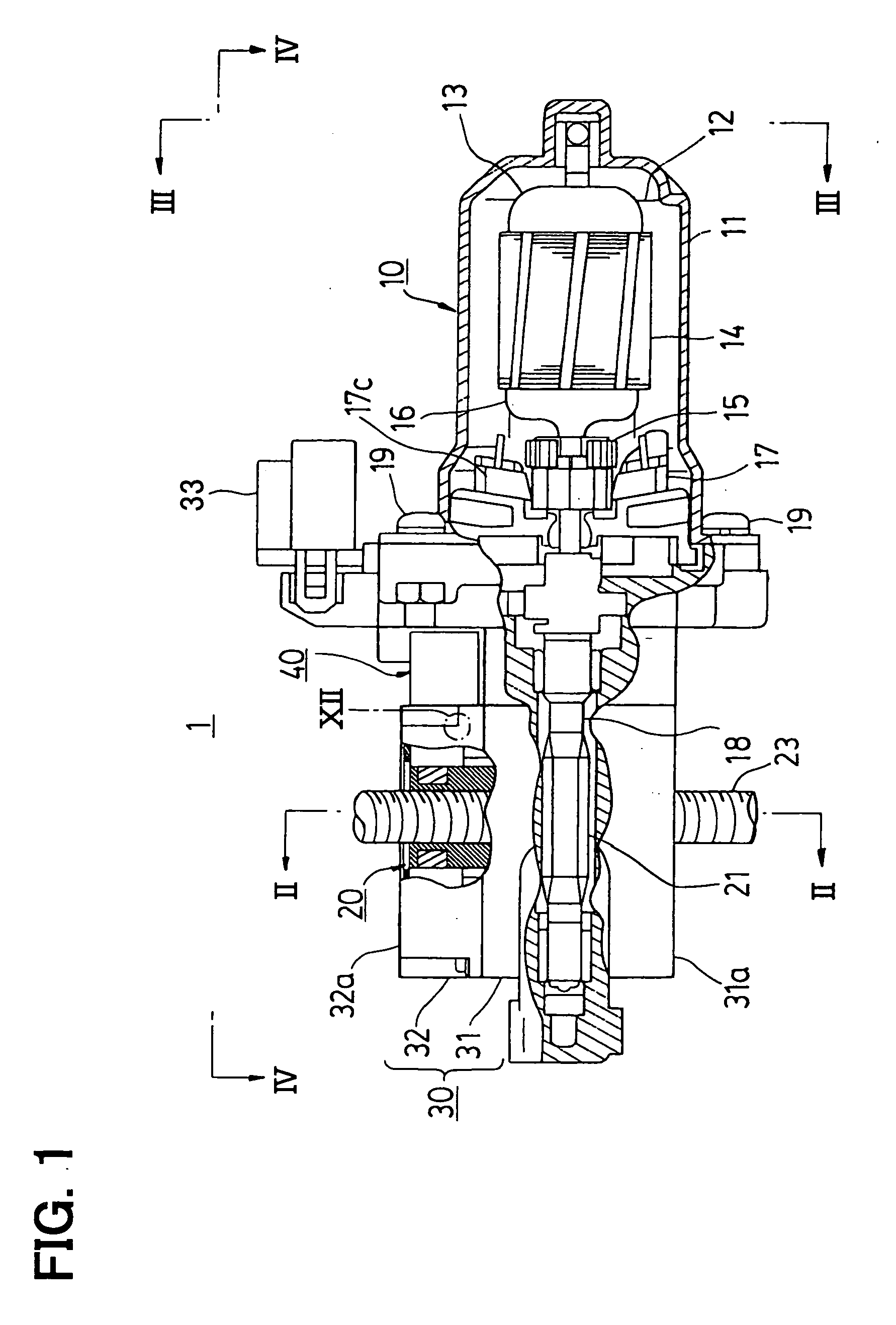
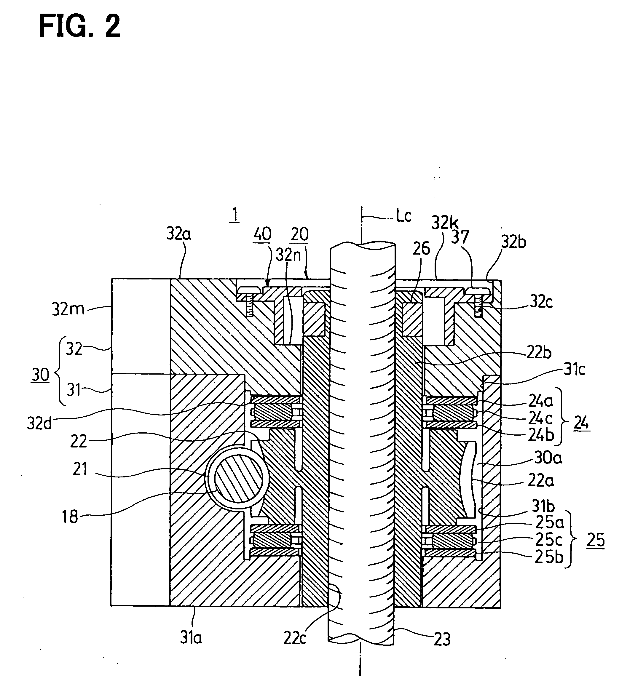
[0035] A structure of a seat drive motor of the present embodiment will be described with reference to FIGS. 1 to 13. Numeral 1 shown in FIG. 1 designates the seat drive motor of the present embodiment. The seat drive motor 1 is suitable for, for example, a lift mechanism of a power seat system S (FIGS. 16 and 17) described later and includes an electric motor unit 10, a speed reducing mechanism 20, a resin gear housing (a housing of the present invention) 30 and a sensor unit (a space member of the present invention) 40.

[0036] With reference to FIG. 1, the motor unit 10 is made of a direct current (DC) brush motor and is connected to the gear housing 30 by screws 19. In th...


PUM


Abstract

A housing includes a support surface that supports an axial force of a worm wheel. Ribs are arranged radially inward of a peripheral wall of one end of the housing and at least partially overlaps with the worm wheel in the axial direction of the rotatable member. Ribs contact a bracket and support the support surface of the gear housing relative to the bracket in the axial direction of the worm wheel when the axial force of the worm wheel is applied to the ribs.

Description

CROSS REFERENCE TO RELATED APPLICATION [0001] This application is based on and incorporates herein by reference Japanese Patent Application No. 2003-399625 filed on Nov. 28, 2003 and Japanese Patent Application No. 2004-298963 filed on Oct. 13, 2004. BACKGROUND OF THE INVENTION [0002] 1. Field of the Invention [0003] The present invention relates to a seat drive motor and a power seat system having the same. More particularly, the present invention relates to a seat drive motor, which includes a housing installed in a vehicle seat through a bracket, and also relates to a power seat system having the same. [0004] 2. Description of Related Art [0005] For example, Japanese Unexamined Patent Publication No. H8-40119 discloses a lift mechanism of a vehicle power seat system. In the lift mechanism, a seat drive motor, which has a speed reducing mechanism, drives a threaded shaft to linearly and axially move the threaded shaft in a forward or backward direction. When the threaded shaft is ...

Claims


Application Information

Patent Timeline
Patent Type & Authority Applications(United States)
IPC IPC(8): B60N2/16B60N2/02B60N2/06B60N2/90F16H25/20H02K7/06H02K7/116
CPCB60N2/0232F16H25/20F16H2025/209Y10T74/19828B60N2002/0236Y10T74/18576H02K7/06B60N2/02253B60N2/02246
Inventor SAKAMAKI, RYOUSUKE
Owner DENSO CORP
Why Eureka
Try Eureka