Motor, robot, substrate loader, and exposure apparatus

Inactive Publication Date: 2005-06-02
NIKON CORP
View PDF9 Cites 39 Cited by
  • Summary
  • Abstract
  • Description
  • Claims
  • Application Information

AI Technical Summary

Benefits of technology

[0028] According to another aspect of the invention, there is provided a substrate loader including at least one arm to load a substrate, an extension mechanism provided with the at least one arm to extend the at least one arm, a raising and lowering mechanism provided with the at least one arm to raise and/or lower the at least one arm, an electromagnetic rotation type motor acting as a drive source for the extension mechanism and the raising and lowering mechanism, and a microrotation mechanism provided with the at least one arm to microrotate the at least one arm.
[0029] According to another aspect of the invention, the substrate loa

Problems solved by technology

This occurs because vibration increases when operating at high speed, since rigidity of the mechanism portion of the substrate loader does not increase.
However, even when the aforementioned measures are implemented, when the wafer conveyance operation is performed during exposure, vibration is generated due to the driving of the conveyance robot (loader), a magnetic field is generated from, for example, the motor built into the robot, and pattern accuracy is reduced.
Although such an electromagnetic rotation type motor is typically compact, lightweight, energy efficient, and able to be controlled, AC magnetic field leakage from the

Method used


Image

  • Motor, robot, substrate loader, and exposure apparatus
  • Motor, robot, substrate loader, and exposure apparatus
  • Motor, robot, substrate loader, and exposure apparatus

Examples


Embodiment Construction

[0048] Reference will now be made in detail to embodiments of the present invention, examples of which are illustrated in the accompanying drawings, wherein like reference numerals refer to the like elements throughout. The embodiments are described below to explain the present invention by referring to the figures.

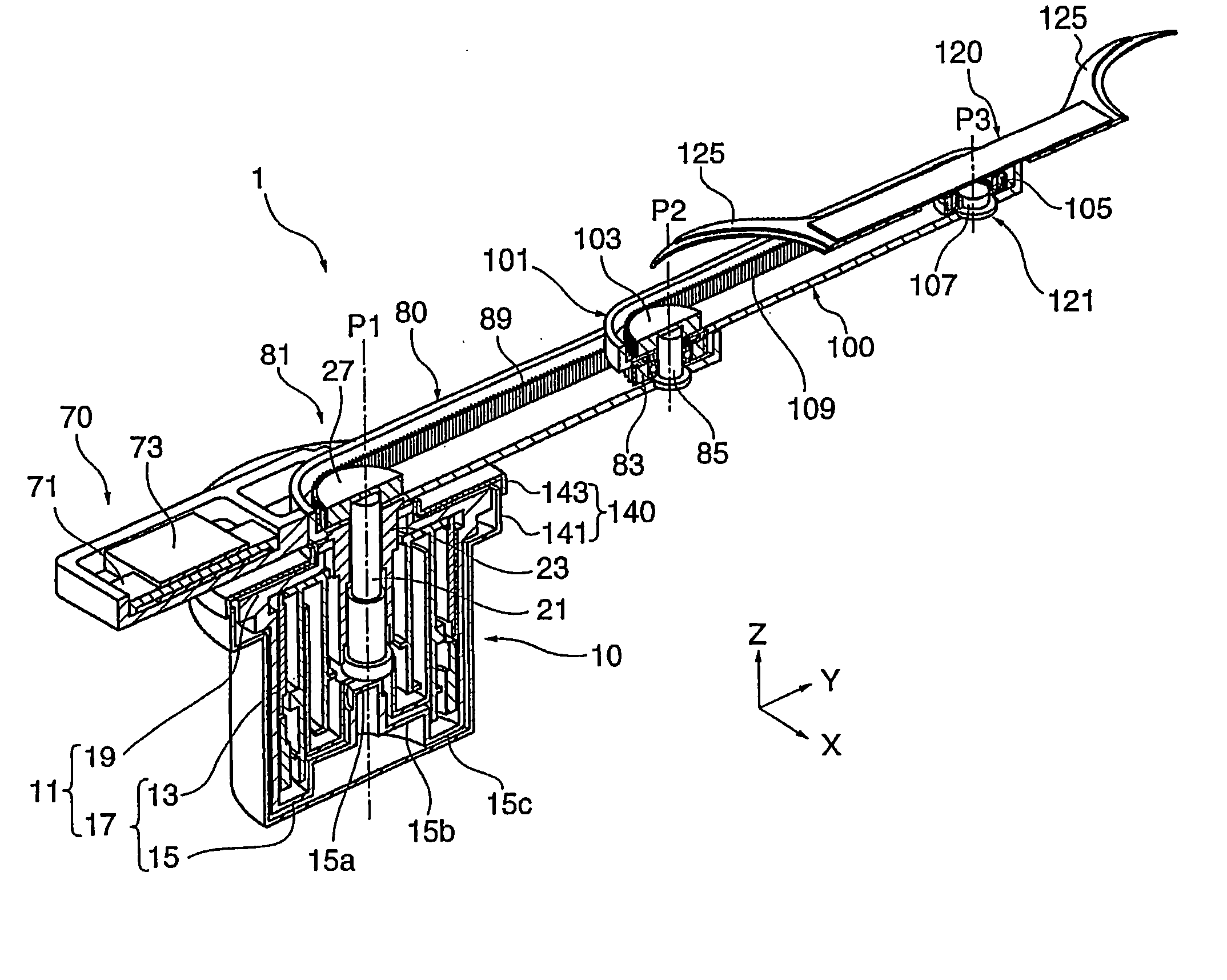
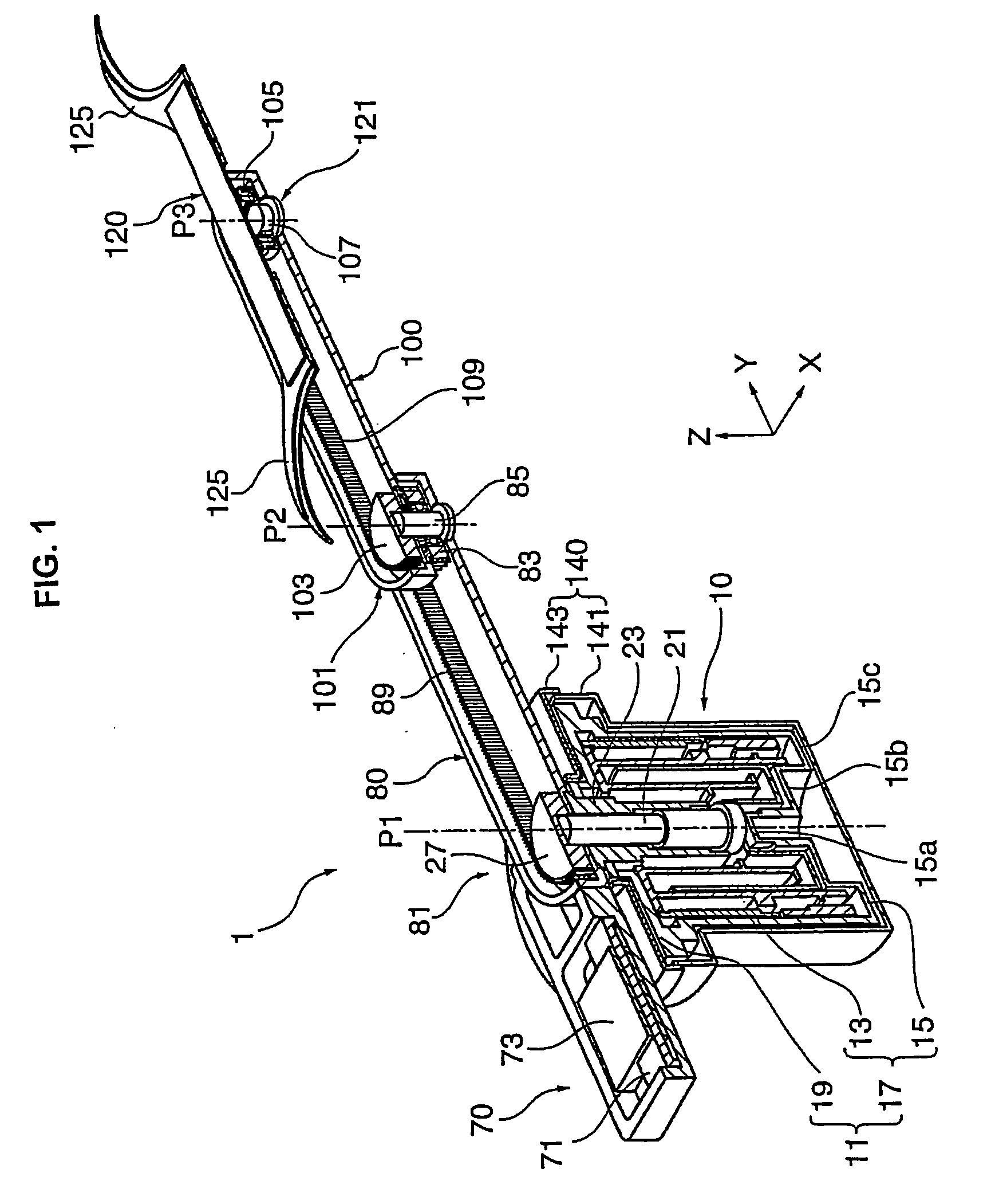
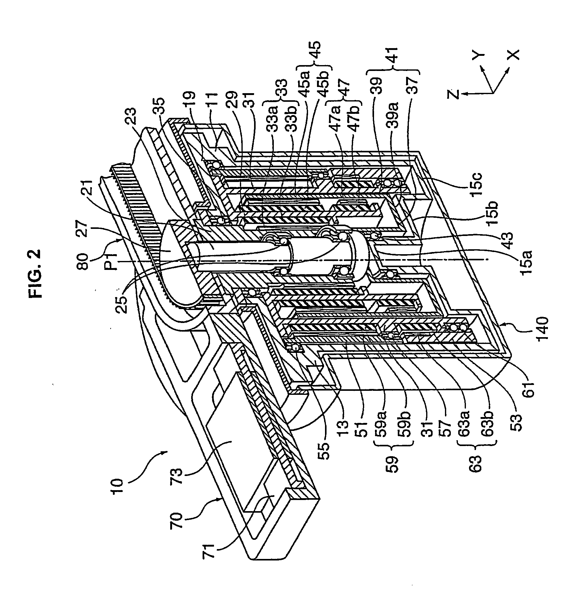
[0049] According to various aspects of the present invention, the aforementioned problems are taken into account, and there is provided a robot equipped with a motor that restricts vibration generation and magnetic leakage. In particular, one embodiment of the invention relates to a substrate loader that includes a type of robot that is capable of handling an end effector at a high speed and an exposure apparatus equipped with the substrate loader.

[0050] According to an embodiment of the invention, the robot includes a first motor equipped with a drive shaft, a main rotor linked with the drive shaft, and a main stator that opposes the main rotor and causes an electromag...


PUM


Abstract

An apparatus that reduces vibration generation and magnetic leakage, wherein the apparatus is a motor, an articulated serial robot that has a motor built in, a substrate loader that includes the articulated robot, and a related exposure apparatus equipped with the substrate loader. The motor includes a drive shaft to drive the motor; a rotor attached with the shaft; and a stator that opposes the rotor and causes an electromagnetic force to act between the rotor and the stator to drive the drive shaft; an RC stator, for reaction force cancellation attached with the stator; an RC rotor for reaction force cancellation, opposing the RC stator; and a counterweight sleeve attached with the RC rotor, wherein the reaction force, which is applied to the stator via the drive shaft when the counterweight sleeve rotates in a direction opposite that of the drive shaft, is cancelled.

Description

CROSS-REFERENCE TO RELATED APPLICATIONS [0001] This is a continuation application, filed under 35 U.S.C. §111(a), of International Application PCT / JP2003 / 008308 filed on Jun. 30, 2003, the contents of which are incorporated herein by reference.BACKGROUND OF THE INVENTION [0002] 1. Field of the Invention [0003] The present invention relates to a motor that has added improvements to reduce vibration generation and magnetic leakage as well as an articulated serial robot that has a motor built in. In addition, the present invention relates to a substrate loader that includes an articulated serial robot, with added improvements to reduce or restrict vibration and increase high speed handling performance, and / or as well as an exposure apparatus equipped with the substrate loader. [0004] 2. Description of the Related Art [0005]FIG. 14 illustrates a formation-related apparatus and control system overview of an entire optical system of an electron beam exposure apparatus of a projection expo...

Claims


Application Information

Patent Timeline
IPC IPC(8): B25J9/04B25J9/12B25J18/04G01N35/04G03F7/20H02K7/02H02K7/04H02K7/116H02K7/14H02K11/00H02K16/02H02K21/12H02K26/00H02K41/035
CPCB25J9/042Y10T74/20317B25J18/04B82Y10/00B82Y40/00G01N2035/0475G03F7/7075G03F7/70766H01J37/3174H01J37/32743H01J2237/204H02K7/02H02K7/04H02K7/116H02K7/14H02K11/0005H02K16/02H02K16/025H02K21/12H02K26/00H02K41/0356Y02E60/16B25J9/126H02K11/0141
Inventor TANAKA, KEIICHI
Owner NIKON CORP
Why Eureka
Try Eureka