Break-away gas check for muzzle-loading firearms

a technology of firearms and gas check, which is applied in the direction of weapons, missile propulsion, ammunition projectiles, etc., can solve the problems of significant reduction in the efficiency of such firearms, malformed when being placed, and destructive interactions between bullets and bores

Inactive Publication Date: 2005-06-02
CROWSON HAROLD
View PDF32 Cites 11 Cited by
  • Summary
  • Abstract
  • Description
  • Claims
  • Application Information

AI Technical Summary

Benefits of technology

[0011] The present invention provides a gas check member for use in muzzle-loading firearms. The gas check member is desig

Problems solved by technology

In this manner, the bullet was frictionally secured in place over the powder charge and engaged with the rifling of the bore, but was often malformed when being so placed.
Significant reductions in the efficiency of such firearms often result from destructive interactions between the bullet and bore.

Method used


Image

  • Break-away gas check for muzzle-loading firearms
  • Break-away gas check for muzzle-loading firearms
  • Break-away gas check for muzzle-loading firearms

Examples


Embodiment Construction

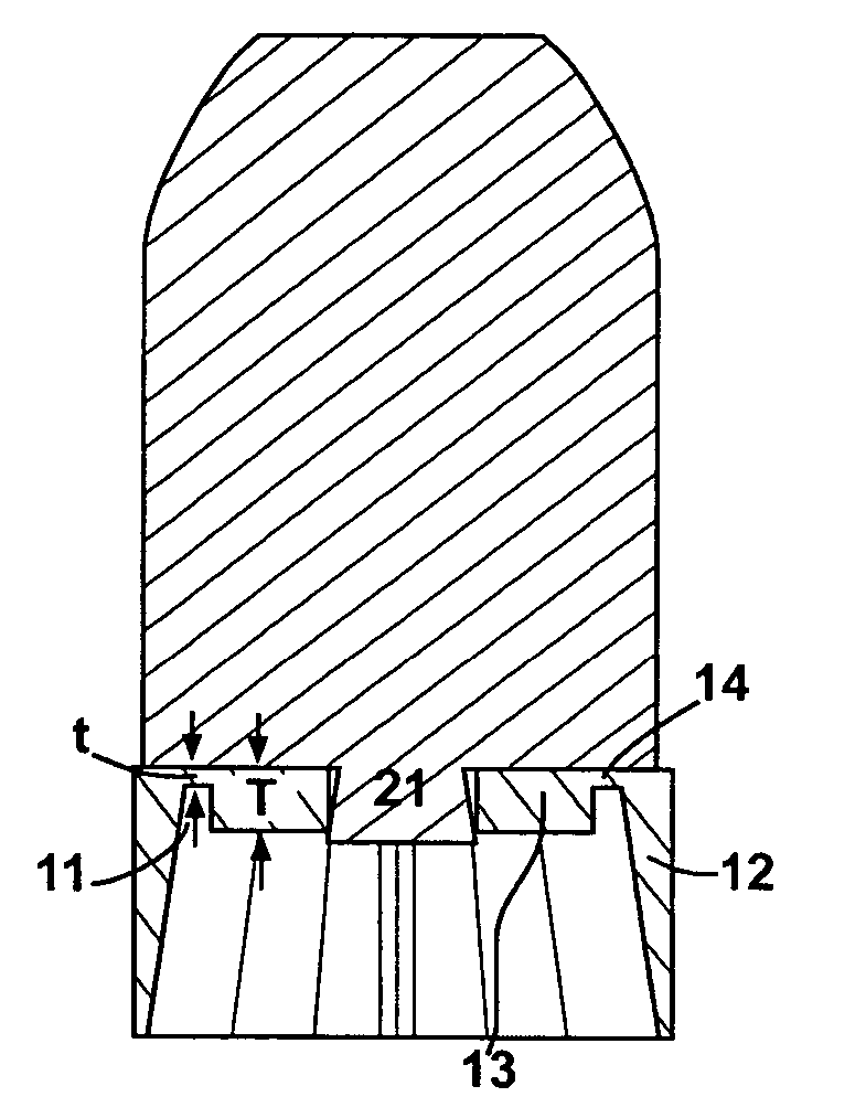
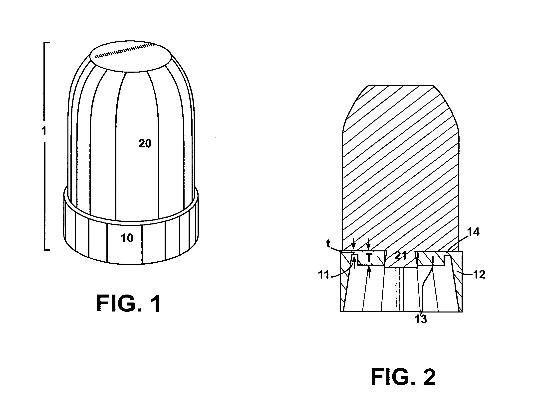
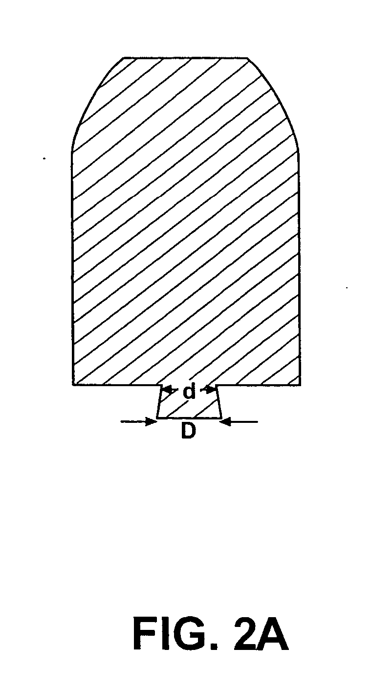
[0024] Referring to the Figures, there are shown several, but not the only, embodiments of the invented gas check member. The gas check is designed for use in combination with a bullet, and therefore is drawn in combination with a bullet in FIGS. 1, 2, 4, 5, and 7. The combination of a gas check member with a bullet will herein be referred to as a projectile.

[0025] In FIGS. 1-5, gas check member 10 comprises a generally cylindrical element preferably constructed of a resilient plastic material and engineered to attach rearward of the maximum diameter of the bullet 20, as shown in FIGS. 1 and 2. The maximum diameter of the bullet is preferably slightly less than that of the bore, and the diameter of the gas check member exceeds that of both bullet and bore 50. This relationship is illustrated in FIG. 4. Bullets used in muzzle-loading firearms are typically composed of a suitable solid, but deformable, material such as lead, and exhibit a tapered cylindrical, ogive or blunted ogive d...


PUM


Abstract

A gas check member, for use in muzzle-loading firearms, frictionally attaches rearward of a sub-caliber bullet to maximize the efficiency of such firearms. The diameter of the gas check preferably exceeds that of the bore slightly to prevent scoring and deformation of the bullet during loading, to hold the projectile in place within the barrel and to prevent moisture from contacting the powder when in place. Upon firing, the gas check minimizes the escape of propellant gases around the projectile and imparts a large, uniformly distributed forward thrust to the bullet to maximize the ballistic qualities of the shot. The gas check preferably incorporates an unstable connection between inner and outer members of the gas check that fractures, at about the time the bullet exits the barrel, to facilitate quick and reliable detachment of the outer member from the bullet. The outer member may also be adapted, preferably by scoring or other weakening of selected regions of the outer member, to itself fracture into multiple pieces, further optimizing detachment or release of a substantial portion of the gas check from the bullet. A more consistent and complete detachment or release helps prevent interference of the gas check with the trajectory of the bullet upon exit from the barrel.

Description

[0001] This application is a continuation-in-part of Non-Provisional patent application Ser. No. 10 / 259,374, filed Sep. 27, 2002, issuing on Jul. 20, 2004 as U.S. Pat. No. 6,763,765, the disclosure of which is incorporated herein by this reference, and claims priority of Provisional Application Ser. No. 60 / 325,530, filed Sep. 27, 2001, entitled “Break Away Gas-Check for Muzzle Loading Firearms”.BACKGROUND OF THE INVENTION [0002] 1. Field of the Invention [0003] This invention relates, in general, to the use of muzzle-loading firearms. More specifically, this invention relates to the design and manufacture of projectiles to be used in such firearms. [0004] 2. Related Art [0005] To function most effectively, muzzle-loading firearms preferably involve the use of a bullet in conjunction with some type of wad or gas check member. Throughout the history of such firearms, various configurations that embrace this design principle have been utilized. The wad or gas check is used to secure th...

Claims


Application Information

Patent Timeline
IPC IPC(8): F42B14/02
CPCF42B14/02
Inventor CROWSON, HAROLD
Owner CROWSON HAROLD
Why Eureka
Try Eureka