Fuel system component and method of manufacture

Active Publication Date: 2005-06-02
TI GRP AUTOMOTIVE SYST LLC
View PDF21 Cites 11 Cited by
  • Summary
  • Abstract
  • Description
  • Claims
  • Application Information

AI Technical Summary

Benefits of technology

[0007] Some objects, features and advantages of the present invention include providing a construction for fuel tanks having a fill nipple with a substantially vapor impermeable passage between the fuel tank and a fill pipe, providing a fill nipple that can be readily attached to the shell of the fuel tank, providing a fill nipp

Problems solved by technology

Also, a fill nipple falling within the spirit and scope of the appe

Method used


Image

  • Fuel system component and method of manufacture
  • Fuel system component and method of manufacture

Examples


Embodiment Construction

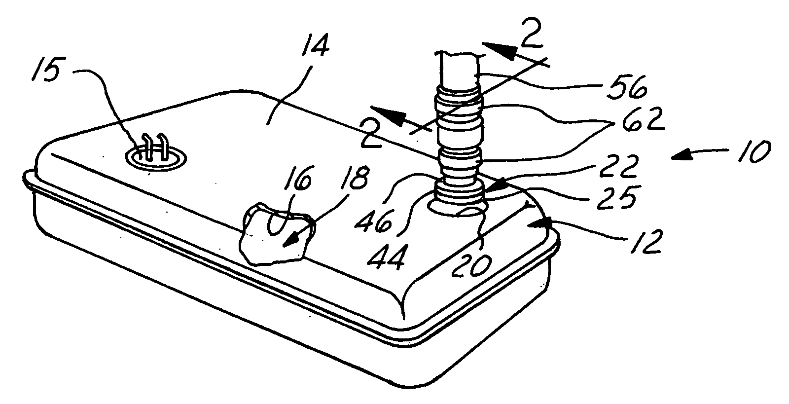
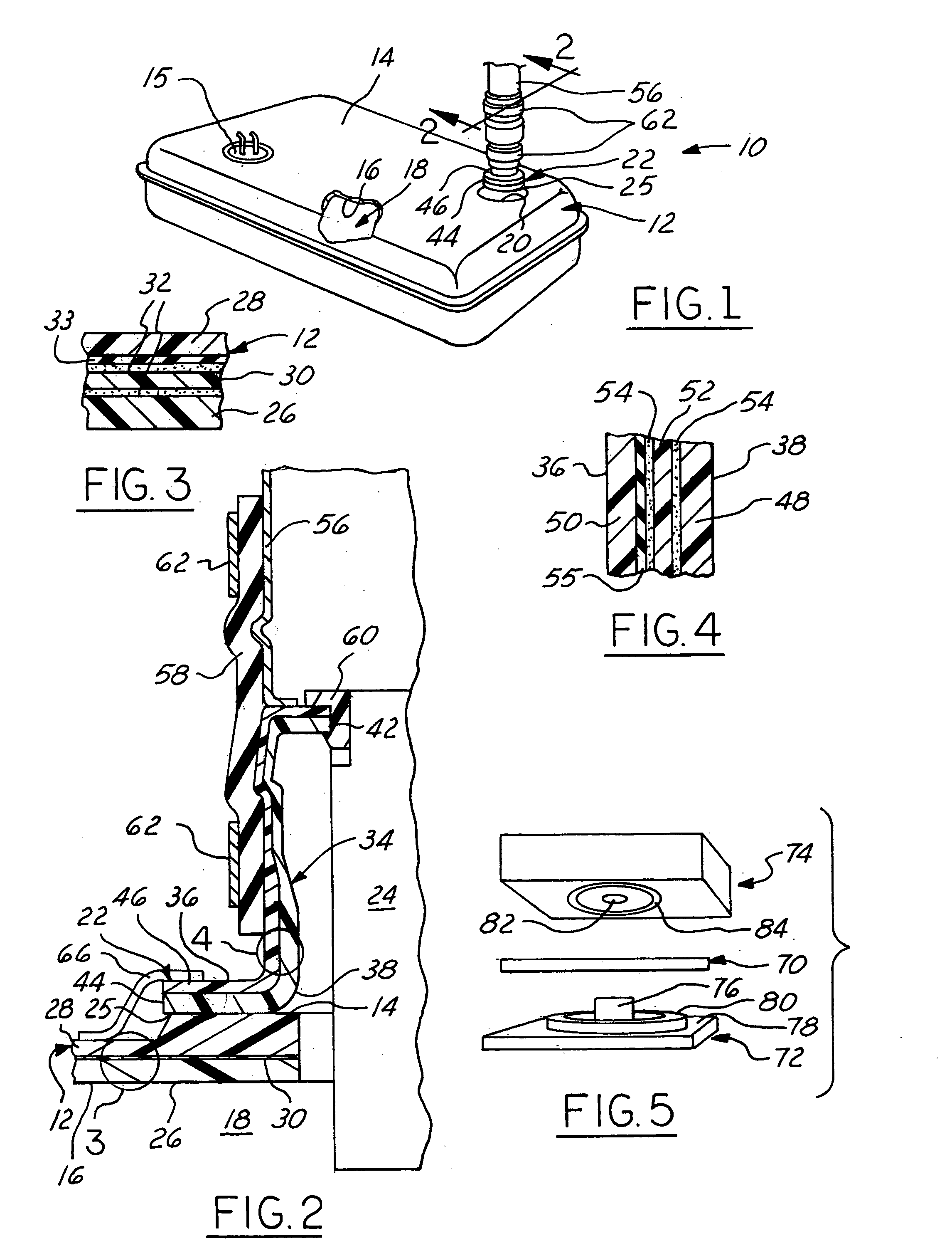
[0015] Referring in more detail to the drawings, FIG. 1 shows one presently preferred embodiment of a fuel tank 10 that has a shell 12 with an outer surface 14 and an inner surface 16 defining a cavity 18 for holding fuel. The shell 12 has a plurality of openings like opening 15 for receiving or providing access to components, for example and without limitation a fuel pump, pressure sensor, fuel level sensor, electrical connectors (all not shown), and an opening 20 for receiving fuel into the cavity 18. A fill nipple 22 is preferably attached to the outer surface 14 of the fuel tank 10 at a joint 25 and has a passage 24 aligned with the opening 20 so that fuel can pass through the passage 24 and into the cavity 18. The construction of the fill nipple 22 resists and preferably substantially prevents fuel vapor permeation therethrough to control and reduce evaporative emissions from the fuel tank 10. In addition, the joint 25 provides a secure attachment of the fill nipple 22 to the s...


PUM

PropertyMeasurementUnit
Temperatureaaaaaaaaaa
Compositionaaaaaaaaaa
Flow rateaaaaaaaaaa

Abstract

A fuel tank that is substantially impermeable to fuel vapor has a shell with an interior for holding fuel, an opening for receiving fuel into the interior, and a fill nipple with a barrier layer. The fill nipple has an outer surface and an inner surface defining a passage extending between a pair of generally opposed ends of the fill nipple. One of the ends is attached to the shell such that the passage is aligned with the opening to allow fuel to flow through the passage and into the interior of the fuel tank. The fill nipple has an inner layer of material forming the inner surface, and an outer layer of material forming the outer surface, and has at least one intermediate layer of material forming the barrier layer. The intermediate layer is formed from a material that is different in composition from the inner and outer layers.

Description

FIELD OF THE INVENTION [0001] This invention relates generally to fuel systems, and more particularly to a fuel system component and a method of making it. BACKGROUND OF THE INVENTION [0002] It is known to blow mold fuel tanks from co-extruded six layer parisons that include inner and outer layers of HDPE, a vapor barrier layer sandwiched between a pair of adhesive layers, and a layer of regrind material between one of the adhesive layers and the outer layer. Wherever the vapor barrier layer is interrupted there is a potential path through which hydrocarbons can more easily escape to the atmosphere from the fuel tank. The vapor barrier layer may be interrupted in, for example, the area of openings through the fuel tank wall and in the area of the pinch or seam formed when the parison is closed for molding. [0003] One opening in the fuel tank is provided to receive fuel into the fuel tank through a fill pipe that is attached to the tank via a fill nipple at one end, and receives a re...

Claims


Application Information

Patent Timeline
IPC IPC(8): B23P17/04B29C49/04B29C49/22B29C49/48B29C51/06B29C51/08B29C51/10B29C51/14B60K15/00B60K15/04B60P3/00
CPCB29C49/04B60K15/04B29C49/4802B29C51/06B29C51/08B29C51/082B29C51/10B29C51/14B29C2049/4807B29C2791/001B29C2791/006B29K2023/065B29K2023/086B29K2025/00B29K2995/0067B29L2031/24B29L2031/7172B29C49/22B29C2049/7862
Inventor BRANDNER, BRIAN W.FRANJO, VLADIMIRKERSEY, KEITH D.KNUEPPEL, HARALD
Owner TI GRP AUTOMOTIVE SYST LLC
Why Eureka
Try Eureka