
Aircraft converts drag to lift

a technology of aircraft and drag, applied in the field of aircraft design, can solve the problems of dragging of 6,256 lb. fuselages and lots of drag, and achieve the effects of less horizontal space, faster or less fuel consumption, and extended flying rang

Inactive Publication Date: 2005-06-02
PAGE JOHN SPLAWN JR
View PDF26 Cites 11 Cited by
  • Summary
  • Abstract
  • Description
  • Claims
  • Application Information

AI Technical Summary

Benefits of technology

[0019] Therefore the above points about air drag are an important part of the subject of this invention.
[0020] Some of the objects and advantages and of this invention are to provide an aircraft that will fly faster or consume less fuel and have an extended flying range. It will also take up less horizontal space on the deck of an aircraft carrier or at an airport terminal docking site. Applicant's accomplishes his goals by converting drag to lift. This allows for wings to be shorter and take up less lateral space.
[0021] In contrast to conventional aircraft that have the alignment of the fuselage and propulsion means on the same alignment, the applicant's invention has the wings on the same alignment as the fuselage. The propulsion means is the thing that is affixed to the fuselage at a different angle: a down angle.
[0022] This feature makes it possible to make a fuselage function as a wing. That important feature along with an unconventional shaped fuselage and wings create a structure that will convert a substantial amount of the costly frontal profile form drag into productive lift. Present aircraft technology is overlooking this potential of using the fuselage as a significant contributor to the lift of the aircraft.
[0023] The Lockheed Martin's S-3 Viking—called the “Swiss Army Knife of Naval Aviation”—remains one of the most successful designs in carrier aircraft history.
[0024] The following is a comparison of the S3 Viking to applicant's design. To compare the S3 Viking to applicant's invention the same square feet of fuselage frontal area is used on each. Each has a fuselage of 77 inches wide by 96 inches high; the square foot of area is 51 feet. The cruising speed of the S3 Viking is 380 knots per hour. The formula for air drag is:

Problems solved by technology

Deduct 75% of the 25,024 and it results in 6,256 lb. fuselages drag.
This is now lift as well as profile drag because the deflection of air is down resulting in lift.
The shape of the front of applicant's wing is not like conventional wings that have a rounded bull nose shape, which causes lots of drag.
There are other types of drag like friction on both type aircraft however since it is not a large amount is not dealt with here.

Method used


Image

  • Aircraft converts drag to lift
  • Aircraft converts drag to lift
  • Aircraft converts drag to lift

Examples


Embodiment Construction

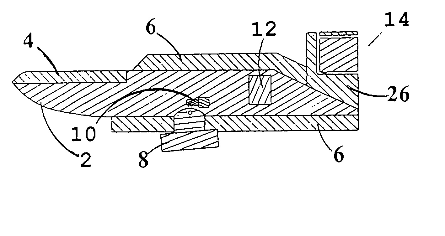
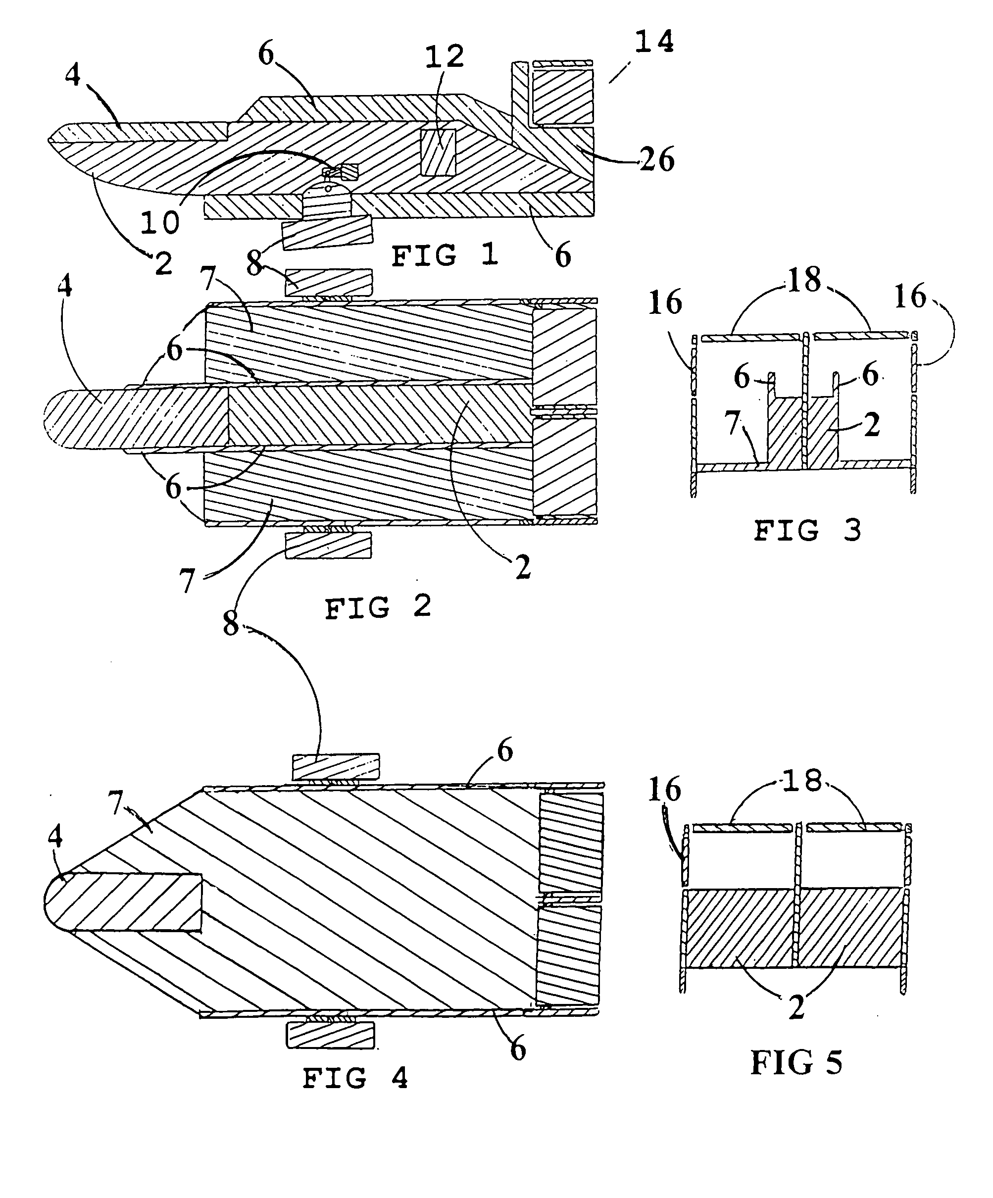
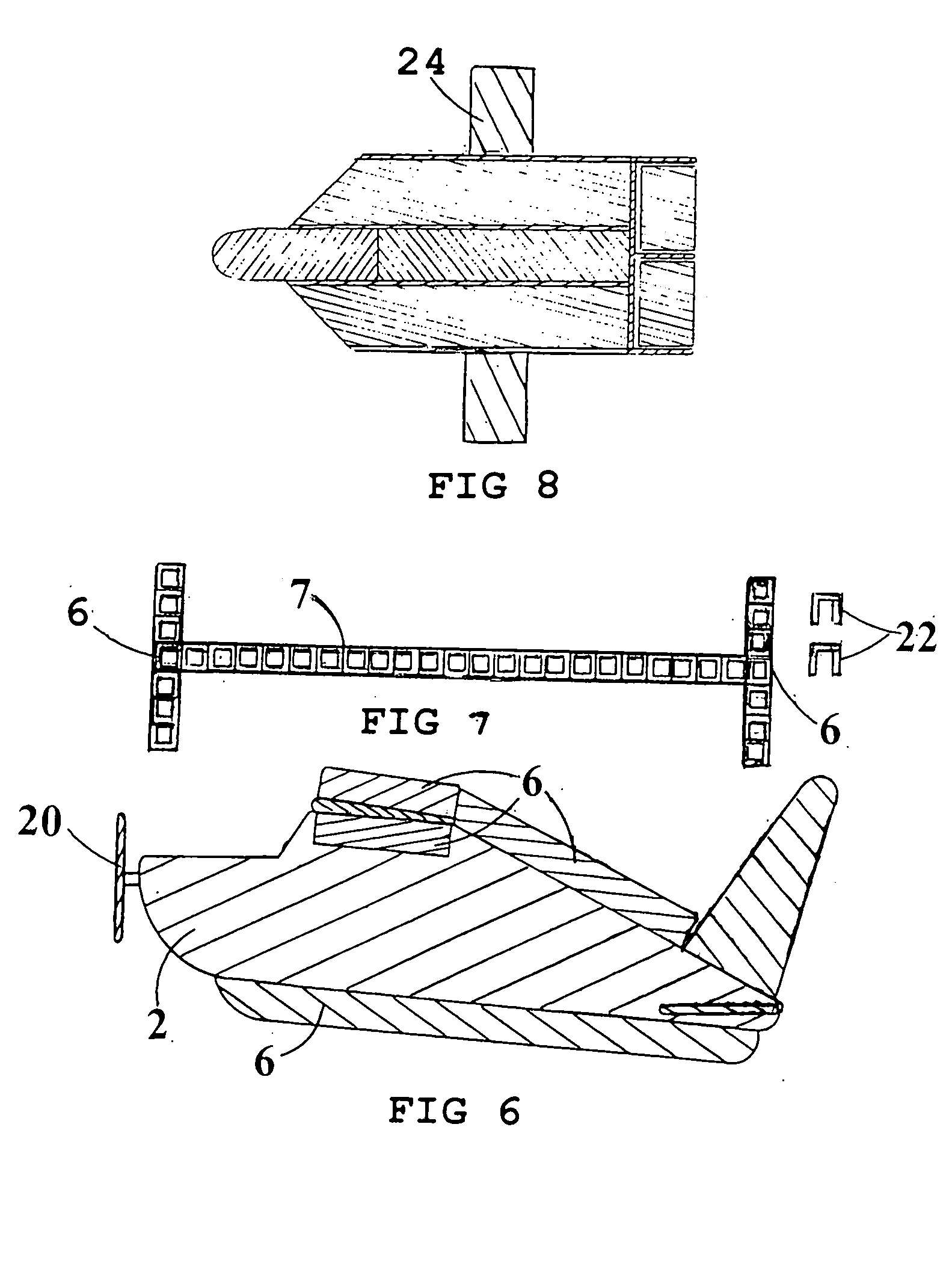
[0055]FIG. 1 is a side view of the aircraft and the fuselage 2. The top, bottom and sides of the fuselage 2 are all flat surfaces. These flat surfaces work well in cooperation with the air-barrier at the sides of the fuselage. The sides being flat give the fuselage lateral stability like the vertical stabilizer of the tail assembly 14 do. They also make it practical to have large flaps 12 operating out of the sides of the fuselage. They give additional turning control and extra slowing capability when landing on an aircraft carrier. FIG. 1 also shows the windshield canopy 4, the air-barrier 6 extending up from the top of the fuselage 2 and extending down from the bottom of the fuselage. Also shown is one of two jet engines 8 with a hydraulic adjusting means 10? It adjusts the up or down alignment of the engine, thereby controlling the direction of the thrust of the engines, one on each side, which adjusts the inclination of the fuselage which determines the amount of lift on the fus...


PUM


Abstract

An aircraft that has a fuselage that has a majority of its frontal surface areas that strike air angled to deflect air down and cause an upward lift on said fuselage and a propulsion means attached to the fuselage on a different angle than the angle of the fuselage thereby causing the bottom of the fuselage to have an angle of attack into the wind like a conventional wing thereby contributing to the lift of the aircraft.

Description

BACKGROUND [0001] This invention relates to aircraft design as it affects speed, fuel consumption, the flying range and the horizontal space that a plane takes up on the deck of an aircraft carrier or at an airport terminal docking site. [0002] When an aircraft pushes the front surfaces of its fuselage and wings through the air a very substantial amount of drag is created. It accounts for a high percent of the total power requirement of an aircraft. [0003] There are several forms or types of drag on an aircraft. The type that applicant's is especially dealing with is the form drag, also called profile drag. Military fighter aircraft are designed with needle nose front ends to minimize this kind of drag. However the larger aircraft such as the famous Lockheed C-130 Hercules, affectionately known as “Fat Albert”, the Boeing 747, and 737-8AS, the Navy work horse S3 Viking and even the new Boeing 777, all have massive profile form drag. [0004] The front of the fuselage on these aircraft...

Claims


Application Information

Patent Timeline
Patent Type & Authority Applications(United States)
IPC IPC(8): B64C1/00B64C3/10B64C5/06B64C5/08B64C39/10
CPCB64C1/0009B64C3/10B64C5/06Y02T50/12B64C39/10B64C2001/0045B64C2039/105B64C5/08Y02T50/10
Inventor PAGE, JOHN SPLAWN JR.
Owner PAGE JOHN SPLAWN JR
Learn More