Light source control module

a control module and light source technology, applied in semiconductor lasers, lighting and heating apparatus, instruments, etc., can solve the problems of shortening the service life of the switch, and the function cannot meet the user's demand, so as to reduce the volume and cost

Inactive Publication Date: 2005-06-02
QUARTON
View PDF2 Cites 11 Cited by
  • Summary
  • Abstract
  • Description
  • Claims
  • Application Information

AI Technical Summary

Benefits of technology

[0007] It is an object of the present invention to provide a light source control module capable of being engaged with a light source main body for making the light source flash with different frequencies.
[0008] It is another object of the present invention to provide a light source control module capable of replacing the conventional back cover device and compactly engaging with the light source main body for achieving portable use, and reducing volume and cost.
[0009] It is yet another object of the present invention to provide a light source control module that is capable of pre-setting and saving the modulation mode in order to control the light source main body to emit a particular flash light for communication purposes.
[0010] In order to accomplish the objects of the present invention, the present invention provides a lighting assembly having a light source main body and a light source control module. The light source main body has a light source that generates light. The light source control module includes a power switch, a housing removably coupled to the light source main body, and a modulation circuit retained inside the housing. The modulation circuit is electrically connected to the power switch for making the light source flash with a frequency when the power switch is turned on. The modulation circuit can have a plurality of modulation modes modulated by an analog method or a digital method. As a result, the light emitted from the light source can have different frequencies.

Problems solved by technology

Since only the simple on / off function is provided, the light source has a limited purpose.
In such conditions, the flashlight must be continuously switched on and off, which will shorten the service life of the switch.
Such functions cannot satisfy a user's demand in certain particular conditions.
For example, for a laser sight used in a gun, when people shoot in a shooting field, a user can hardly recognize the laser spot of his gun from so many different laser spots.

Method used


Image

  • Light source control module
  • Light source control module
  • Light source control module

Examples


Embodiment Construction

[0015] The following detailed description is of the best presently contemplated modes of carrying out the invention. This description is not to be taken in a limiting sense, but is made merely for the purpose of illustrating general principles of embodiments of the invention. The scope of the invention is best defined by the appended claims.

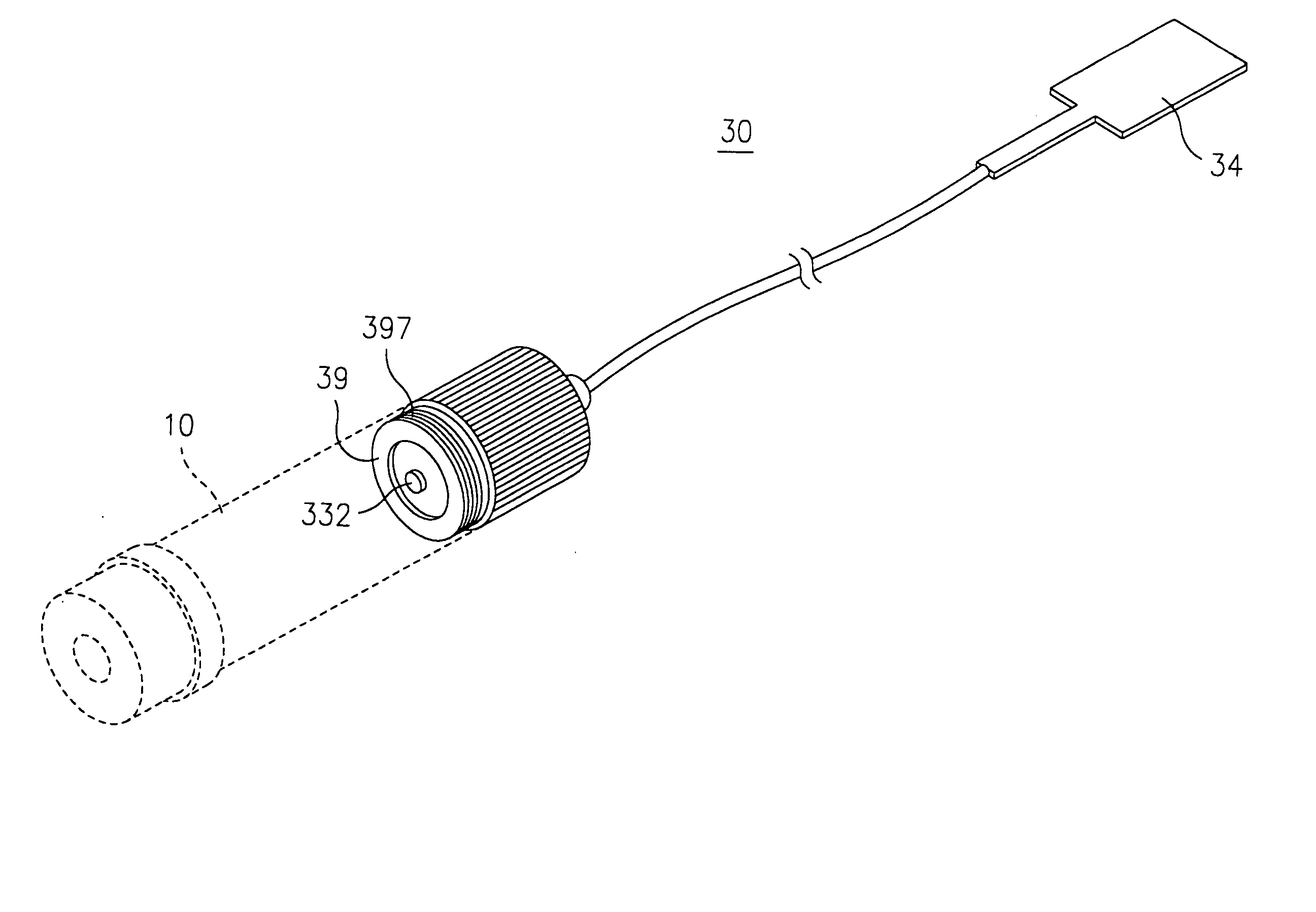
[0016] The light source control module 30 of the present invention can be used for various types of light sources. A laser main body 10 is described as a light source. The light control module 30 of the present invention can be used with the laser main body 10 as a power switch. A laser generator 101 and a battery 102 (providing power for the laser generator 101) are disposed in the laser main body 10. The laser generator 101 can be a conventional laser generator.

[0017] Referring to FIGS. 2 and 3, the light source control module 30 has a housing that includes a cover 31 and a connection sleeve 39. Receiving spaces 312 and 392 are defined inside...


PUM


Abstract

A lighting assembly has a light source main body and a light source control module. The light source main body has a light source that generates light. The light source control module includes a power switch, a housing removably coupled to the light source main body, and a modulation circuit retained inside the housing. The modulation circuit is electrically connected to the power switch for making the light source flash with a frequency when the power switch is turned on.

Description

BACKGROUND OF THE INVENTION [0001] 1. Field of the Invention [0002] The present invention relates to a light source control module, and in particular, to a light source control module having a modulation switch for controlling the light source to emit beams with different modulated frequencies. [0003] 2. Description of the Prior Art [0004] In a conventional light source device, such as a conventional flashlight, LED flashlight or a laser generator, a conventional switch having simple on / off function is used. Since only the simple on / off function is provided, the light source has a limited purpose. As one example, conventional flashlights are turned on and off by a switch so that the flashlight is provided only for emitting light. However, in certain special conditions, it may be desirable to use the flashlight for flashing purposes, such as to provide a continuous flash for getting attention or as a messaging means. In such conditions, the flashlight must be continuously switched on...

Claims


Application Information

Patent Timeline
Patent Type & Authority Applications(United States)
IPC IPC(8): F21V23/04F41G1/35G08B5/00H01S5/022H01S5/042
CPCF41G1/35F21V23/0407
Inventor CHEN, TONY K. T.HSIAO, CHING-HORNGYANG, YU-HSILEE, JAMES
Owner QUARTON
Why Eureka
Try Eureka