Color interpolation method

Inactive Publication Date: 2005-06-02
MEGACHIPS
4 Cites 48 Cited by

AI-Extracted Technical Summary

Problems solved by technology

The interpolation, however, is an operation of estimating image data of a specified pixel from image data of pixels around the specified pixel, and therefore a wrong interpolation is sometimes performed depending on the content of an image.
Since the correlations are obtained only by using the G signals in the methods disclosed in the above Laid Open Gazettes, however, these methods have a problem in accuracy of interpolation.
Since the correlation in the h...

Benefits of technology

[0013] By this method, when there is no evaluable correlation in the horizontal direction or the vertical direction, it is possible to avoid perform...

Abstract

A sensor such as a CCD image pickup device is equipped with a color filter of RGB Bayer array. An image is read from such a sensor (S1) and inputted to a color interpolation device as raw data (S2). The color interpolation device calculates additional values DH and DV of differential absolute values of pixel values in a horizontal direction and a vertical direction by using pixels of all colors in a peripheral area of a specified pixel (S3 and S4). The additional values DH and DV are compared with each other (S5) and when it is judged that there is a tendency of pixel drift in the horizontal direction or the vertical direction, S6 is executed. In S6, when a correlation in the vertical direction is strong, an interpolation using vertical adjacent pixels is performed and when a correlation in the horizontal direction is strong, an interpolation using horizontal adjacent pixels is performed. By this method, it is possible to improve the accuracy of color interpolation.

Application Domain

Television system detailsTelevision system scanning details +3

Technology Topic

Computer visionColor interpolation +1

Image

  • Color interpolation method
  • Color interpolation method
  • Color interpolation method

Examples

  • Experimental program(1)

Example

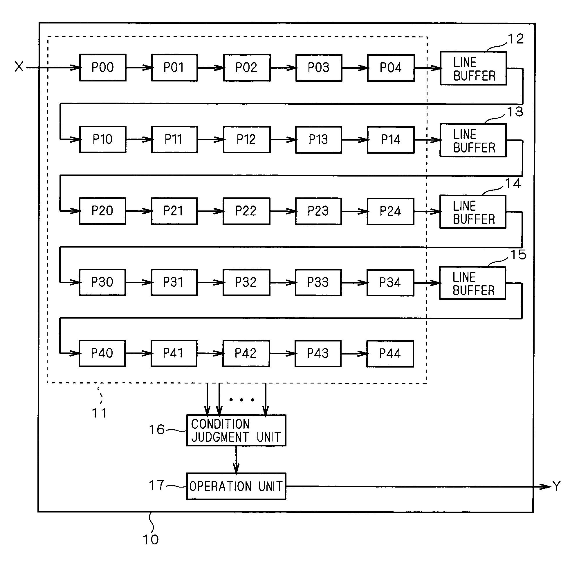
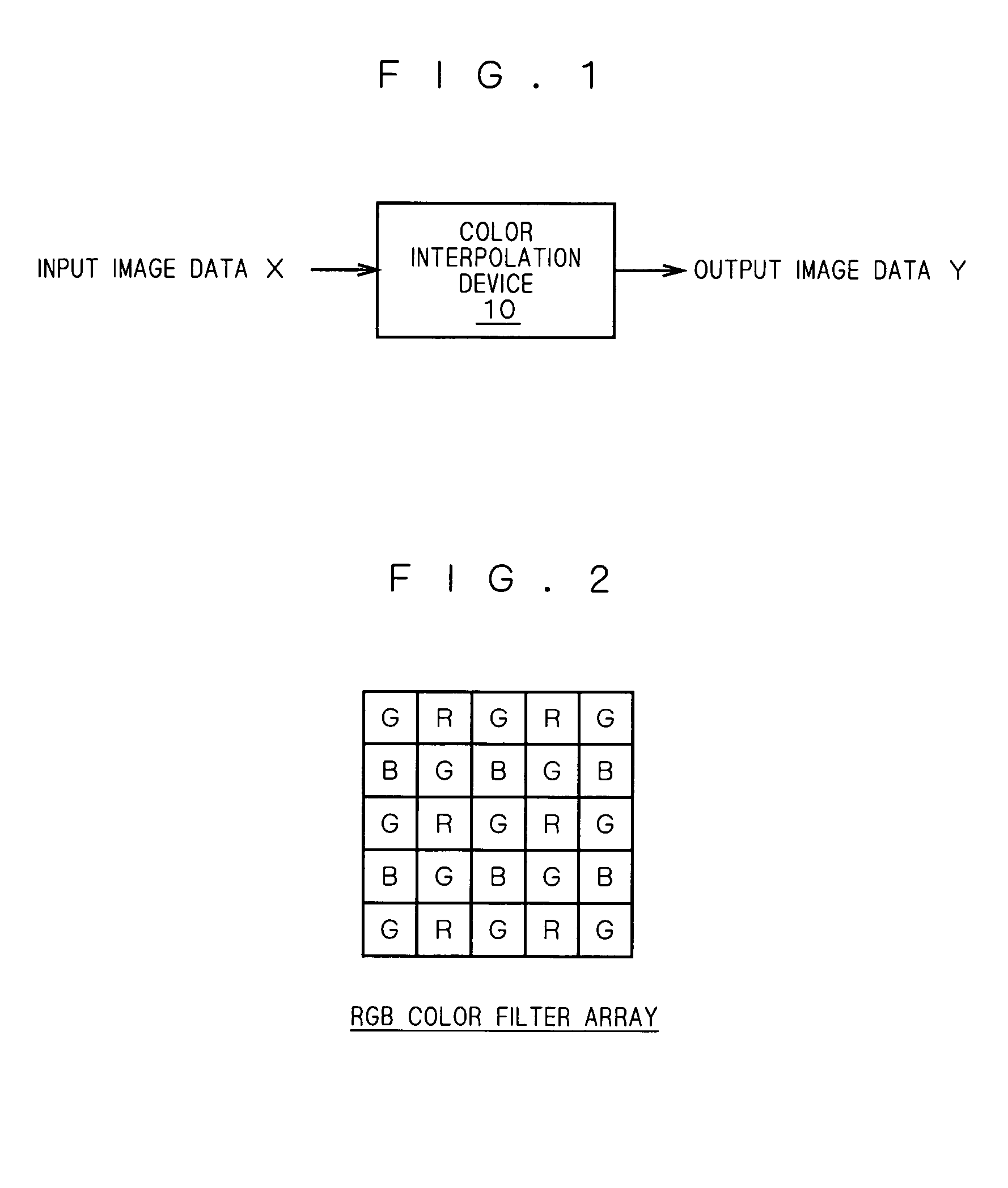
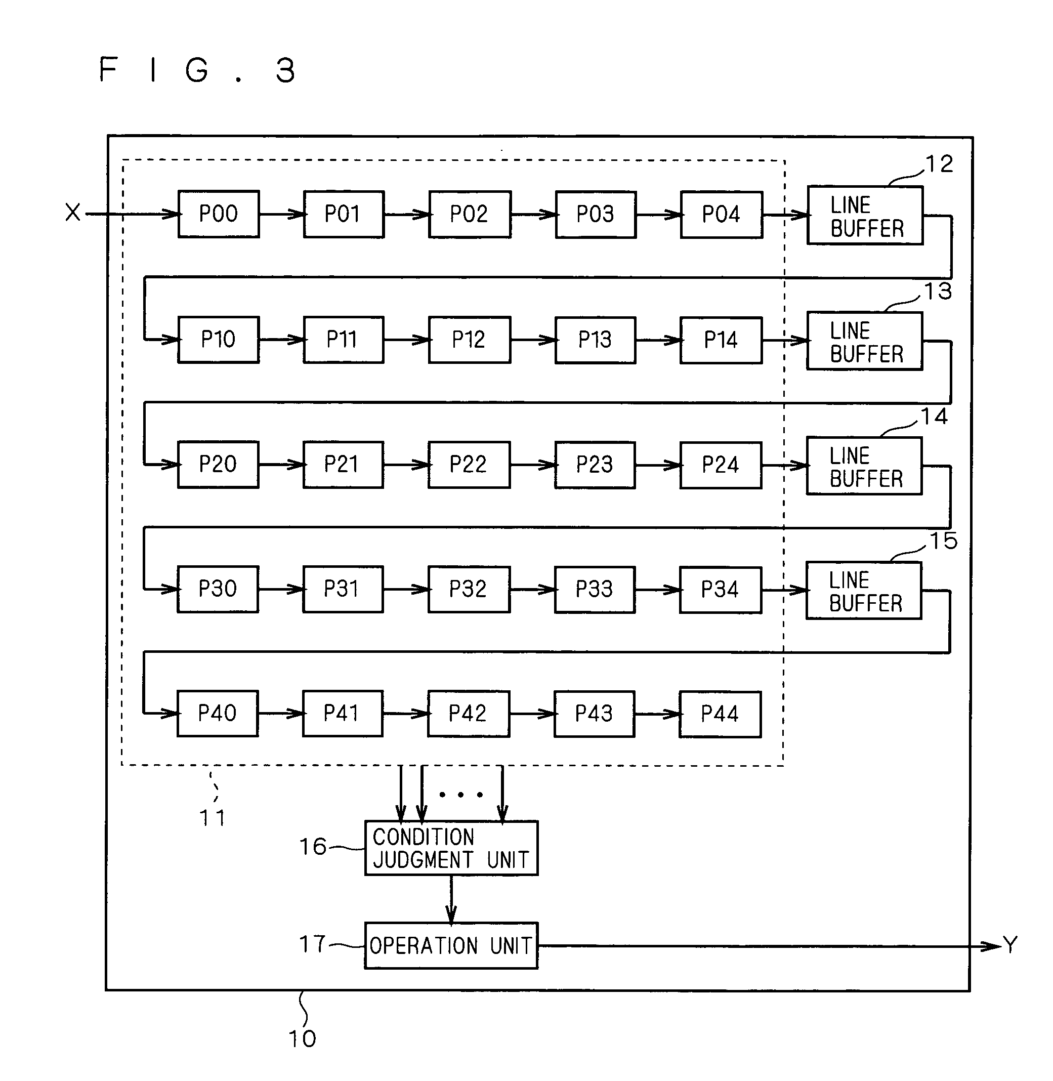
[0023] Hereinafter, the preferred embodiment of the present invention will be discussed, referring to figures. As shown in FIG. 1, a color interpolation device 10 performs color interpolation on input image data X and outputs color-interpolated output image data Y.
[0024] The input image data X is, e.g., data picked up by a CCD image pickup device used in a digital camera. In this preferred embodiment, it is assumed that the CCD image pickup device is a 1-chip CCD having a color filter of RGB Bayer array as shown in FIG. 2. In the RGB Bayer array, G (Green) filters are arranged in a checkered pattern and R (Red) filters and B (Blue) filters are arranged alternately by lines. Therefore, the input image data X is data having a pixel value of any one color of R (Red) component, G (Green) component and B (Blue) component for one pixel. Such input image data X is inputted to the color interpolation device 10 in an order of colors, e.g., G, R, G, R . . . or B, G, B, G . . . or the like.
[0025]FIG. 3 is a functional block diagram showing the color interpolation device 10. The color interpolation device 10 comprises a group of registers 11, line buffers 12, 13, 14 and 15, a condition judgment unit 16 and an operation unit 17. The condition judgment unit 16 and the operation unit 17 have equivalent constitutions constituted of, e.g., a CPU and a memory storing a program defining an operation of the CPU.
[0026] The group of registers 11 comprises twenty-five (5×5) registers P00, P01, . . . P44, as shown in FIG. 3. More specifically, five registers P00 to P04 are connected in series to one another and a line buffer 12 is connected to a lower side of the last register P04. Further, in a downstream (lower side) of the line buffer 12, five registers P10 to P14 are connected in series thereto and the line buffer 13 is connected to a lower side of the last register P14. Further, in a downstream of the line buffer 13, five registers P20 to P24 are connected in series thereto and the line buffer 14 is connected to a lower side of the last register P24 and in a downstream (lower side) of the line buffer 14, five registers P30 to P34 are connected in series thereto and the line buffer 15 is connected to a lower side of the last register P34. Finally, in a downstream (lower side) of the line buffer 15, five registers P40 to P44 are connected in series thereto.
[0027] To the group of registers 11, pixel values of the input image data X are sequentially inputted along a direction of pixel arrangement (direction of scan line). The respective pixel values stored in the registers P00 to P43 are transmitted to the respective lower-side registers P01 to P44 every one clock and stored therein. The pixel values passing through the group of registers 11 go by way of the line buffers 12 to 15. If the input image data X inputted to the color interpolation device 10 is image data of N pixels in a horizontal direction, for example, the line buffers 12 to 15 serve as a line buffer for storing image data of (N-5) pixels. Specifically, the line buffers 12 to 15 receive the data of pixels outputted from the registers P04, P14, P24 and P34, then hold the image data for (N-4) clocks and output the pixel data to the respective next-stage registers P10, P20, P30 and P40 at (N-5) clock. As a result, the group of registers 11 holds two-dimensional pixel value (5×5 pixels) around a specified pixel. In this case, the specified pixel is a pixel corresponding to the register P22.
[0028] Assuming that the pixel values stored in the registers P00, P02, . . . P44 are Q00, Q01, . . . Q44, the group of registers 11 stores the two-dimensional image data as shown in FIG. 4. Specifically, the pixel value of the specified pixel before interpolation is Q22.
[0029] When the input image data X is sequentially inputted to the color interpolation device 10 on a pixel-by-pixel basis, the pixel values Q00, Q01, . . . Q44 of the 5×5 pixels shown in FIG. 4 are stored in the registers P00, P01, . . . P44, respectively, as pixel values of peripheral pixels of the specified pixel. Then, every time when the specified pixel is updated, the condition judgment unit 16 inputs the pixel values Q00, Q01, . . . Q44 of the peripheral pixels stored in the registers P00, P01, . . . P44.
[0030] The condition judgment unit 16 calculates an additional value of differential absolute values of pixel values on the basis of the pixel values Q00, Q01, . . . Q44 for each of the horizontal direction and the vertical direction. This is an operation for obtaining the tendency of pixel drift in the horizontal and vertical directions about the current specified pixel. The tendency of pixel drift indicates the correlation of the pixel values, and for example, when there are straight lines or stripes in the horizontal direction, it is said that there is a tendency of horizontal drift of pixels. When there is a tendency of horizontal drift of pixels, the correlation in the horizontal direction is high.
[0031] The difference of pixel values in the horizontal direction is a difference between values of pixels of the same color which appear every other pixel as shown in FIG. 5. For example, when a horizontal line is a row of pixels R, G, R, G, R . . . , both differences of pixel values for the G component and the R component are calculated. Similarly, when a horizontal line is a row of pixels B, G, B, G, B . . . , both differences of pixel values for the G component and the B component are calculated.
[0032] Eq. 1 is an equation of a pixel-value change evaluation value DH in the horizontal direction, i.e., an additional value of differential absolute values of pixel values in the horizontal direction, where abs (x) represents an absolute value of x. DH = abs ⁡ ( Q ⁢ ⁢ 00 - Q ⁢ ⁢ 02 ) + abs ⁡ ( Q ⁢ ⁢ 01 - Q ⁢ ⁢ 03 ) + abs ⁡ ( Q ⁢ ⁢ 02 - Q ⁢ ⁢ 04 ) + abs ⁡ ( Q ⁢ ⁢ 10 - Q ⁢ ⁢ 12 ) + abs ⁡ ( Q ⁢ ⁢ 11 - Q ⁢ ⁢ 13 ) + abs ⁡ ( Q ⁢ ⁢ 12 - Q ⁢ ⁢ 14 ) + abs ⁡ ( Q ⁢ ⁢ 20 - Q ⁢ ⁢ 22 ) + abs ⁡ ( Q ⁢ ⁢ 21 - Q ⁢ ⁢ 23 ) + abs ⁡ ( Q ⁢ ⁢ 22 - Q ⁢ ⁢ 24 ) + abs ⁡ ( Q ⁢ ⁢ 30 - Q ⁢ ⁢ 32 ) + abs ⁡ ( Q ⁢ ⁢ 31 - Q ⁢ ⁢ 33 ) + abs ⁡ ( Q ⁢ ⁢ 32 - Q ⁢ ⁢ 34 ) + abs ⁡ ( Q ⁢ ⁢ 40 - Q ⁢ ⁢ 42 ) + abs ⁡ ( Q ⁢ ⁢ 41 - Q ⁢ ⁢ 43 ) + abs ⁡ ( Q ⁢ ⁢ 42 - Q ⁢ ⁢ 44 ) ( Eq . ⁢ 1 )
[0033] Eq. 2 is an equation of a pixel-value change evaluation value DV in the vertical direction, i.e., an additional value of differential absolute values of pixel values in the vertical direction, where abs (x) represents an absolute value of x. DH = abs ⁡ ( Q ⁢ ⁢ 00 - Q ⁢ ⁢ 20 ) + abs ⁡ ( Q ⁢ ⁢ 10 - Q ⁢ ⁢ 30 ) + abs ⁡ ( Q ⁢ ⁢ 20 - Q ⁢ ⁢ 40 ) + abs ⁡ ( Q ⁢ ⁢ 01 - Q ⁢ ⁢ 21 ) + abs ⁡ ( Q ⁢ ⁢ 11 - Q ⁢ ⁢ 31 ) + abs ⁡ ( Q ⁢ ⁢ 21 - Q ⁢ ⁢ 41 ) + abs ⁡ ( Q ⁢ ⁢ 02 - Q ⁢ ⁢ 22 ) + abs ⁡ ( Q ⁢ ⁢ 12 - Q ⁢ ⁢ 32 ) + abs ⁡ ( Q ⁢ ⁢ 22 - Q ⁢ ⁢ 42 ) + abs ⁡ ( Q ⁢ ⁢ 03 - Q ⁢ ⁢ 23 ) + abs ⁡ ( Q ⁢ ⁢ 13 - Q ⁢ ⁢ 33 ) + abs ⁡ ( Q ⁢ ⁢ 23 - Q ⁢ ⁢ 43 ) + abs ⁡ ( Q ⁢ ⁢ 04 - Q ⁢ ⁢ 24 ) + abs ⁡ ( Q ⁢ ⁢ 14 - Q ⁢ ⁢ 34 ) + abs ⁡ ( Q ⁢ ⁢ 24 - Q ⁢ ⁢ 44 ) ( Eq . ⁢ 2 )
[0034] The pixel-value change evaluation values DH and DV are values obtained by adding up the differential absolute values of the same color pixels arranged every other pixel in an area of the peripheral pixels of 5×5 as shown in FIG. 4 in the horizontal direction and the vertical direction, respectively. These evaluation values DH and DV add up the differential absolute values of all color components of R, G and B.
[0035] Next, the condition judgment unit 16 calculates a differential absolute value abs (DH−DV) between the pixel-value change evaluation value DH of the horizontal direction and the pixel-value change evaluation value DV of the vertical direction and judges whether Eq. 3 is satisfied or not.
abs(DH−DV)≧DA (Eq. 3)
where DA represents a threshold value for judging the tendency of pixel drift in the horizontal direction or the vertical direction. When the difference between the pixel-value change evaluation value DH in the horizontal direction and the pixel-value change evaluation value DV in the vertical direction is not too much large and the differential absolute value is smaller than the threshold value DA, it is judged that there is no tendency of pixel drift in the horizontal direction or the vertical direction, in other words, it is judged that there is no evaluable correlation in either the horizontal direction or the vertical direction and the interpolation of the present invention is not needed. On the other hand, when the differential absolute value is larger than the threshold value DA, it is judged that there is a tendency of pixel drift in the horizontal direction or the vertical direction, in other words, it is judged that there is an evaluable correlation in either the horizontal direction or the vertical direction and the interpolation of the present invention is needed.
[0036] The condition judgment unit 16 informs the operation unit 17 of the judgment result on the correlation. In accordance with this result, the operation unit 17 performs an interpolating operation. Specifically, when the condition judgment unit 16 judges that Eq. 3 is satisfied, in other words, when it is judged that there is an evaluable correlation in either the horizontal direction or the vertical direction, the operation unit 17 performs such an interpolating operation as shown in Eq. 4. Qi ⁢ ⁢ 22 = Q ⁢ ⁢ 12 + Q ⁢ ⁢ 32 2 ⁢ ⁢ ( DH DV ) ⁢ ⁢ Qi ⁢ ⁢ 22 = Q ⁢ ⁢ 21 + Q ⁢ ⁢ 23 2 ⁢ ⁢ ( DH DV ) Eq . ⁢ 4
where Qi22 represents an interpolated pixel value about the specified pixel. When DH>DV, in other words, when the correlation in the vertical direction is larger, an average value of the vertical adjacent pixel values Q12 and Q32 of the specified pixel is adopted as a pixel value of the specified pixel. When DH 21 and Q23 of the specified pixel is adopted as a pixel value of the specified pixel.
[0037] As shown in Eq. 4, the interpolation is performed by using the vertical or horizontal adjacent pixel values. Accordingly, when the input image data X is image data of RGB Bayer array as shown in FIG. 2, the image data of G component can be subjected to the interpolation. Therefore, in the preferred embodiment, the color interpolation device 10 performs interpolation of the image data of G component.
[0038] Depending on the arrangement of the color filters, however, the color interpolation can be performed on the other color components, i.e., R component and B component, by applying the algorithm of the present invention. Specifically, the characteristic feature of the color interpolation algorithm of the present invention lies in that for judging the tendency of pixel drift in the horizontal direction or the vertical direction, i.e., for judging the correlation, the pixel-value change evaluation values DH and DV are calculated by using the pixel values of all the color components in a color space. As far as the pixel-value change evaluation values DH and DV are used as judgment references, these values may be applied to the interpolating operations for the R component and the B component as well as the G component.
[0039] Though the input image data X is image data in the RGB color space in the above-discussed preferred embodiment, the algorithm of the present invention can be applied to a case where the input image data is data in other color spaces. Further, though the pixel-value change evaluation values DH and DV are obtained by using the 5×5 pixels around the specified pixel in the above-discussed preferred embodiment, an area of the peripheral pixels used for calculation of the pixel-value change evaluation values DH and DV is not particularly limited but a peripheral area of 7×7 pixels may be used.
[0040]FIG. 7 is a flowchart showing the color interpolation algorithm of the present invention. First, a sensor such as a CCD image pickup device reads an image (Step S1). Next, the color interpolation device 10 inputs the input image data X as raw data (Step S2). Subsequently, the color interpolation device 10 calculates an additional value of the differential absolute values in the horizontal direction (the pixel-value change evaluation value DH in the horizontal direction) and an additional value of the differential absolute values in the vertical direction (the pixel-value change evaluation value DV in the vertical direction) (Steps S3 and S4).
[0041] Next, the condition judgment unit 16 judges whether there is a tendency of pixel drift in the horizontal direction or the vertical direction or not (Step S5). In this judgment, whether Eq. 3 is satisfied is judged.
[0042] When it is judged that there is a tendency of pixel drift in the horizontal direction or the vertical direction, in other words, when it is judged that there is an evaluable correlation in either the horizontal direction or the vertical direction (YES in Step S5), such an interpolation as shown in Eq. 4 is performed (Step S6).
[0043] On the other hand, when it is judged that there is no tendency of pixel drift in the horizontal direction or the vertical direction, in other words, when it is judged that there is no evaluable correlation in either the horizontal direction or the vertical direction (NO in Step S5), other well-known interpolation is performed since the interpolation of Eq. 4 is not appropriate. Among other interpolations is, for example, a method using an average value of the vertical and horizontal adjacent four pixels as a pixel value of the specified pixel. Further, an interpolating operation disclosed in Japanese Patent Application Laid Open Gazette No. 11-225056 and the like, which is applied by the present applicant, may be performed.
[0044] Thus, when the relation between the pixel-value change evaluation values DH and DV does not satisfy Eq. 3, the interpolation of Eq. 4 is not performed for the following reason. The interpolation algorithm of the present invention is used for performing an interpolation when there is a correlation in the horizontal direction or the vertical direction, in consideration of the correlation. Accordingly, the interpolation adopts biased data as compared with, e.g., the interpolation using the vertical and horizontal adjacent four pixels. Therefore, especially when there is no correlation in either the horizontal direction or the vertical direction, the interpolation of Eq. 4 is not performed and the interpolation using the conventional algorithm is adopted.
[0045] While the invention has been shown and described in detail, the foregoing description is in all aspects illustrative and not restrictive. It is therefore understood that numerous modifications and variations can be devised without departing from the scope of the invention.

PUM

no PUM

Description & Claims & Application Information

We can also present the details of the Description, Claims and Application information to help users get a comprehensive understanding of the technical details of the patent, such as background art, summary of invention, brief description of drawings, description of embodiments, and other original content. On the other hand, users can also determine the specific scope of protection of the technology through the list of claims; as well as understand the changes in the life cycle of the technology with the presentation of the patent timeline. Login to view more.

Similar technology patents

Imaging apparatus and flicker detection method

ActiveUS20100013953A1reduce dependencyimprove accuracy
Owner:RENESAS ELECTRONICS CORP

Emotion classifying method fusing intrinsic feature and shallow feature

ActiveCN105824922AImprove classification performanceimprove accuracy
Owner:CHONGQING UNIV OF POSTS & TELECOMM

Scene semantic segmentation method based on full convolution and long and short term memory units

InactiveCN107480726Aimprove accuracylow resolution accuracy
Owner:UNIV OF ELECTRONIC SCI & TECH OF CHINA

Classification and recommendation of technical efficacy words

  • improve accuracy

Golf club head with adjustable vibration-absorbing capacity

InactiveUS20050277485A1improve grip comfortimprove accuracy
Owner:FUSHENG IND CO LTD

Stent delivery system with securement and deployment accuracy

ActiveUS7473271B2improve accuracyreduces occurrence and/or severity
Owner:BOSTON SCI SCIMED INC

Method for improving an HS-DSCH transport format allocation

InactiveUS20060089104A1improve accuracyincrease benefit
Owner:NOKIA SOLUTIONS & NETWORKS OY

Catheter systems

ActiveUS20120059255A1increase selectivityimprove accuracy
Owner:ST JUDE MEDICAL ATRIAL FIBRILLATION DIV

Gaming Machine And Gaming System Using Chips

ActiveUS20090075725A1improve accuracy
Owner:UNIVERSAL ENTERTAINMENT CORP
Why Eureka
Try Eureka