Eureka AIR delivers breakthrough ideas for toughest innovation challenges, trusted by R&D personnel around the world.

Video signal receiving apparatus and video signal receiving method, and video signal recording/reproducing apparatus and video signal recording/reproducing method

Inactive Publication Date: 2005-06-02
KK TOSHIBA
View PDF2 Cites 0 Cited by
  • Summary
  • Abstract
  • Description
  • Claims
  • Application Information

AI Technical Summary

Problems solved by technology

Thus, the television cannot acquire the frequency information for viewing limit and the viewing limit cannot be achieved.

Method used


Image

  • Video signal receiving apparatus and video signal receiving method, and video signal recording/reproducing apparatus and video signal recording/reproducing method
  • Video signal receiving apparatus and video signal receiving method, and video signal recording/reproducing apparatus and video signal recording/reproducing method
  • Video signal receiving apparatus and video signal receiving method, and video signal recording/reproducing apparatus and video signal recording/reproducing method

Examples


Embodiment Construction

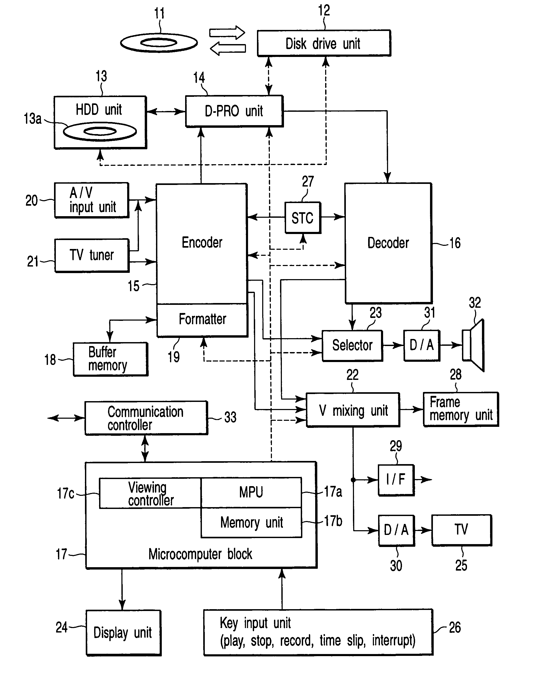
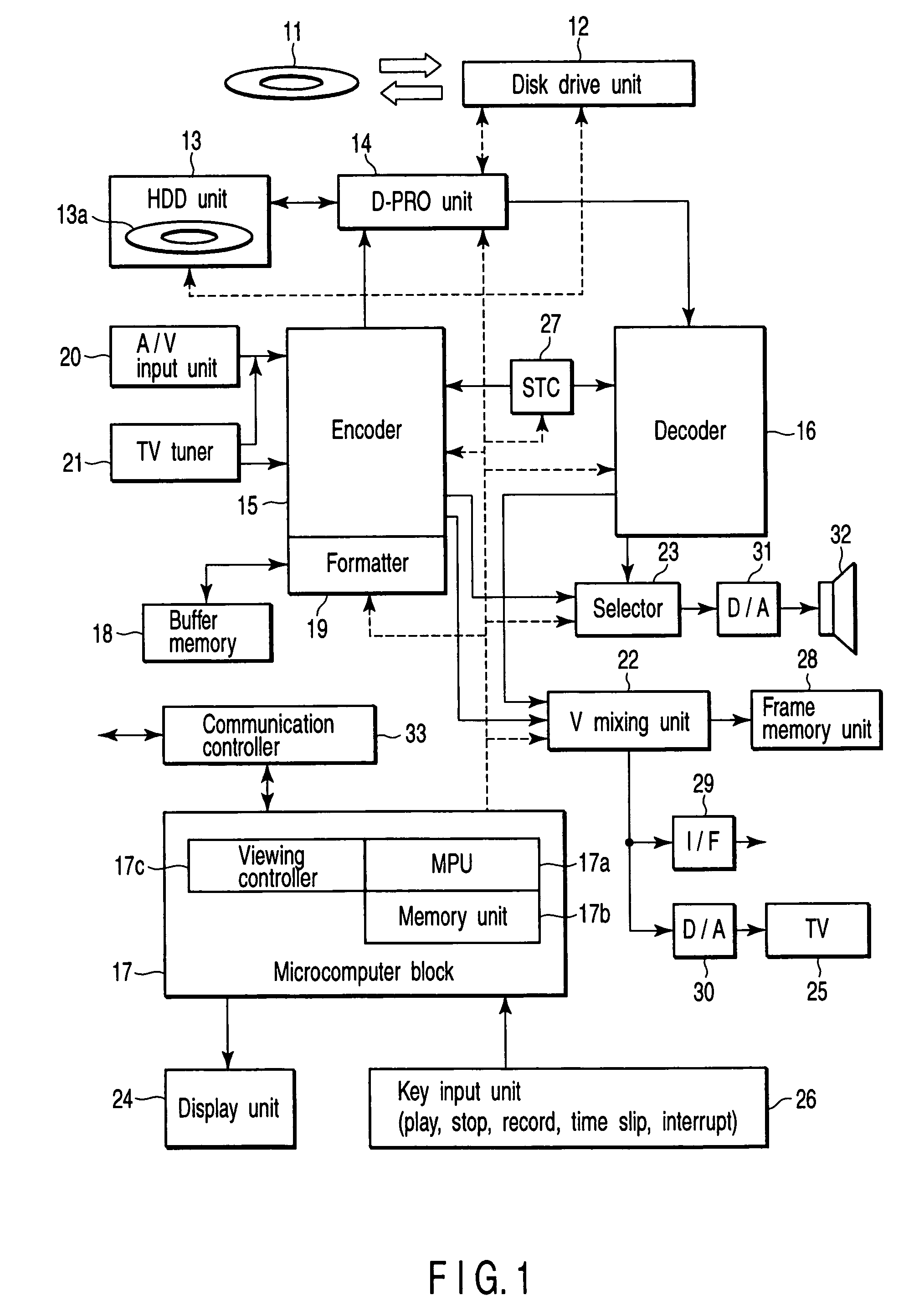
[0024] One embodiment according to the present invention will be described below in detail with reference to the drawings. FIG. 1 shows in detail an optical disk recording / reproducing apparatus to be explained in this embodiment. This optical disk recording / reproducing apparatus is configured to handle both an optical disk such as DVD that is recordable as a recording medium and a hard disk, but, for example, a semiconductor memory may be employed for the recording medium.

[0025] In other words, the optical disk recording / reproducing apparatus shown in FIG. 1 is roughly divided into a main block for recording on the left of the drawing, a main block for reproducing on the right thereof, and a main block for control on the bottom thereof.

[0026] This optical disk recording / reproducing apparatus has two types of disk drive units. The apparatus has a disk drive unit 12 which rotation-drives an optical disk 11 as a first medium which is an information recording medium capable of constru...


PUM


Abstract

The video signal receiving apparatus comprises a receiving unit configured to receive a video signal on which frequency information for viewing limit is multiplexed during a video blanking period of a specific line in an interlace system, an output unit configured to selectively output the received video signal in an interlaced state or in a state of being converted into a progressive video signal, a detecting unit configured to detect the frequency information for viewing limit which is multiplexed during the video blanking period from the received video signal, and a controller configured to limit an output of the video signal from the output unit when the output unit is requested to output a progressive video signal in a state where the frequency information is detected.

Description

CROSS-REFERENCE TO RELATED APPLICATIONS [0001] This application is based upon and claims the benefit of priority from prior Japanese Patent Application No. 2003-400904, filed Nov. 28, 2003, the entire contents of which are incorporated herein by reference. BACKGROUND OF THE INVENTION [0002] 1. Field of the Invention [0003] The present invention relates to a video signal receiving apparatus and a video signal receiving method for receiving and video-displaying, for example, TV broadcasting or the like. The present invention further relates to a video signal recording / reproducing apparatus and a video signal recording / reproducing method for recording / reproducing a video signal in a recording medium such as disk. [0004] 2. Description of the Related Art [0005] As is well known, in recent years, a high-density recording technique for information has been promoted, and an optical disk having a recording capacity of 4.7 GB (Giga Byte) per layer on one side has been made practical. [0006] ...

Claims


Application Information

Patent Timeline
IPC IPC(8): G11B20/10H04N5/44H04N5/91H04N5/913H04N7/01H04N7/08H04N7/081H04N7/088
CPCH04N5/913H04N7/088H04N21/235H04N21/4334H04N2005/91328H04N21/44204H04N21/4542H04N21/4627H04N21/8355H04N21/440218
Inventor HISATOMI, SHUICHI
Owner KK TOSHIBA
Why Eureka
Eureka Blog
Learn More