Multiple energy x-ray source for security applications

a technology of energy x-ray and security applications, applied in the field of security applications with multiple energy x-ray sources, can solve problems such as ambient radiation levels in excess of acceptable standards

Inactive Publication Date: 2005-06-02
AMERICAN SCI & ENG INC
View PDF49 Cites 74 Cited by
  • Summary
  • Abstract
  • Description
  • Claims
  • Application Information

AI Technical Summary

Benefits of technology

[0014] In additional embodiments, the inspection system may include at least one ambient radiation monitor for creating a signal based on radiation detected outside an exclusion zone and a controller for regulating the intensity of the sources based at least on the signal. The source may be pulsed and the controller may regulate the number of beam pulses per unit time based on the signal.

Problems solved by technology

However, a container of dense material may still shield the characteristic x-rays emitted by such material from detection.
However, this approach implicates the duration and flux of the x-ray pulse and may result in ambient levels of radiation in excess of acceptable standards.

Method used


Image

  • Multiple energy x-ray source for security applications
  • Multiple energy x-ray source for security applications
  • Multiple energy x-ray source for security applications

Examples


Embodiment Construction

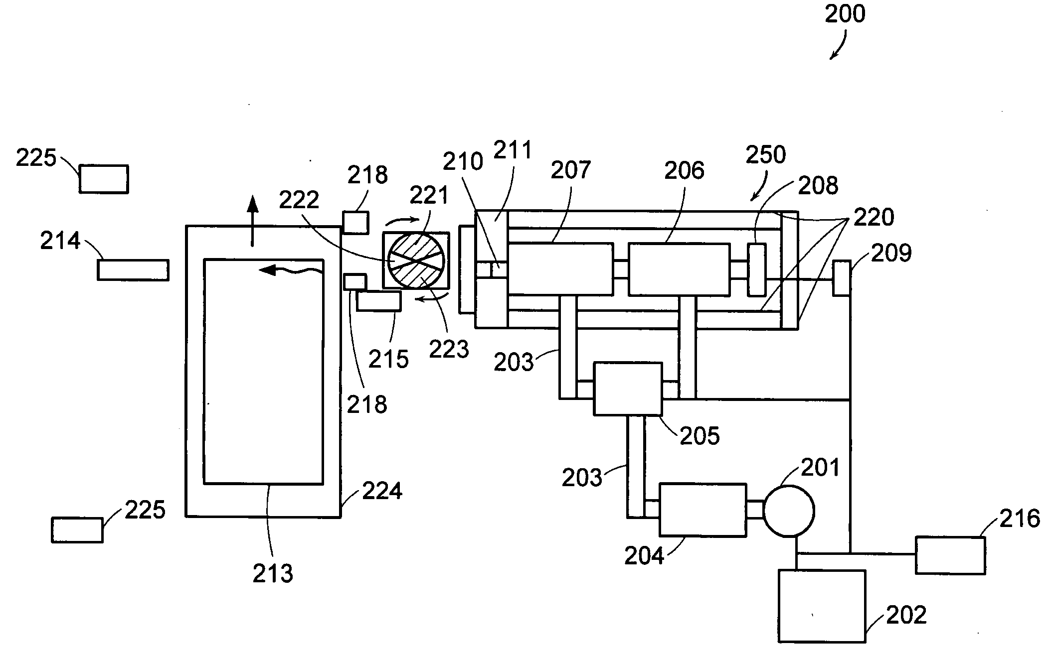
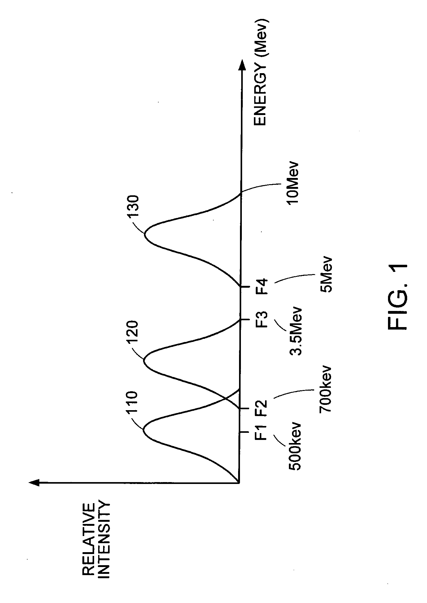
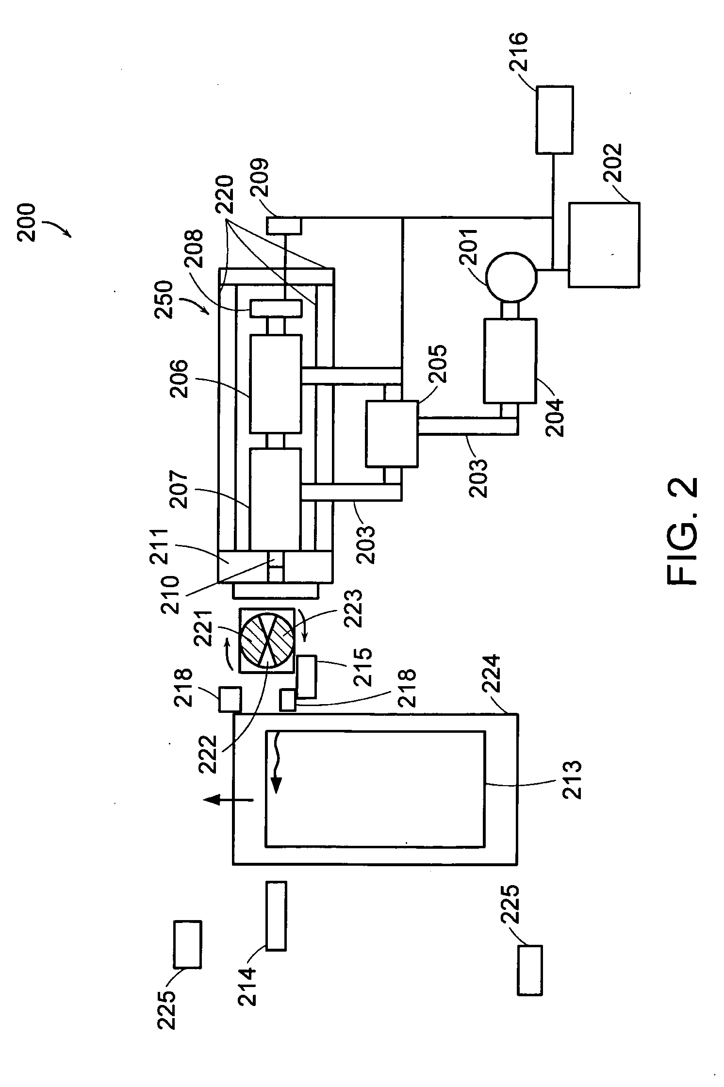
[0025] This invention takes advantage of the fact that the spectra of x-rays generated by accelerating electrons into a target, as provided by individual or multiple linear accelerators (“linacs”), may be tailored to cover distinct energy ranges. Use of such distinct spectra, as produced by a linac having a Shaped Energy™ option (see U.S. Pat. No. 6,459,761, “Spectrally Shaped X-Ray Inspection System,” issuing Oct. 1, 2002, hereby incorporated by reference) may allow for material identification within dense cargo while holding leakage dose rates to cabinet level specifications. A security system may also include backscatter recognition capability for organic recognition, as described, for example, in U.S. Pat. No. 5,313,511.

[0026] With a higher end of the linac energy range above a threshold of 7-10 MeV so as to be adequate for generating sufficient photo-neutron flux, reliable fissile material recognition capability may be provided by neutron detectors, even if the fissile materia...


PUM

PropertyMeasurementUnit
energyaaaaaaaaaa
energyaaaaaaaaaa
instantaneous energyaaaaaaaaaa

Abstract

An x-ray inspection system for identifying fissile material includes one or more sources of penetrating radiation that generate first, second, and third instantaneous spectra where the object is exposed to the second only if there is no penetration of the first and the object is exposed to the third only if there is no penetration of the second. Further, the sources of the second and the third spectra are pulsed. Consequently, ambient levels of radiation may be held below cabinet levels while identifying objects containing fissile material.

Description

CROSS REFERENCE TO RELATED APPLICATIONS [0001] The present application is a continuation-in-part of a U.S. patent application with Ser. No. 10 / 750,178, which is a continuation-in-part application of a U.S. patent application with Ser. No. 09 / 818,987 filed Mar. 27, 2001, which claims priority from a U.S. Provisional Application with Ser. No. 60 / 192,425, filed Mar. 28, 2000 and is a continuation-in-part application of a U.S. patent application with Ser. No. 10 / 156,989, filed May 29, 2002, which claims priority from a U.S. Provisional Application with Ser. No. 60 / 360,854, filed Mar. 1, 2002. The present application is also a continuation-in-part of a U.S. patent application with Ser. No. 10 / 161,037, which is a continuation-in-part of a U.S. patent application with Ser. No. 09 / 502,093, filed Feb. 10, 2000, and of a U.S. patent application with Ser. No. 09 / 919,352, filed Jul. 30, 2001. The disclosures of all of the above applications are incorporated herein, in their entirety, by referen...

Claims


Application Information

Patent Timeline
Patent Type & Authority Applications(United States)
IPC IPC(8): G01N23/02G01N23/04G01N23/20G01T3/06G01V5/00G21K5/10
CPCG01N23/02G01N23/04G01N23/20G21K5/10G01V5/0041G01V5/0091G01T3/06G01V5/0069
Inventor MISHIN, ANDREYSAPP, WADEGRODZINS, LEEROTHSCHILD, PETER
Owner AMERICAN SCI & ENG INC
Why Eureka
Try Eureka