Optical fiber cable and method of manufacturing therefor

a technology of optical fiber and fiber optic cables, applied in the direction of optics, fibre mechanical structures, instruments, etc., can solve the problems of low tensile strength of optical fibers, easy damage, and difficulty in controlling water pressure to be sprayed, so as to reduce physical impact

Inactive Publication Date: 2005-06-02
SAMSUNG ELECTRONICS CO LTD
View PDF8 Cites 12 Cited by
  • Summary
  • Abstract
  • Description
  • Claims
  • Application Information

AI Technical Summary

Benefits of technology

[0011] Another object of the present invention is to provide an optical fiber cable including an external sheath capable of reducing physical impact caused by irregularly formed recesses and having a plurality of recesses with uniform depth and diameter.

Problems solved by technology

However, these optical fibers have low tensile strength due to a material characteristic thereof, so that they are easily damaged under certain external circumstances.
However, it is difficult to control water pressure to be sprayed, and the recesses are irregularly formed as water flows through the external sheath.
In addition, recesses having irregular depths and diameters cause deviation of air distribution applied to the optical fiber cable during the air-blown installation.
This causes the optical fiber cable to be bent or damaged during the air-blown installation.

Method used


Image

  • Optical fiber cable and method of manufacturing therefor
  • Optical fiber cable and method of manufacturing therefor
  • Optical fiber cable and method of manufacturing therefor

Examples


first embodiment

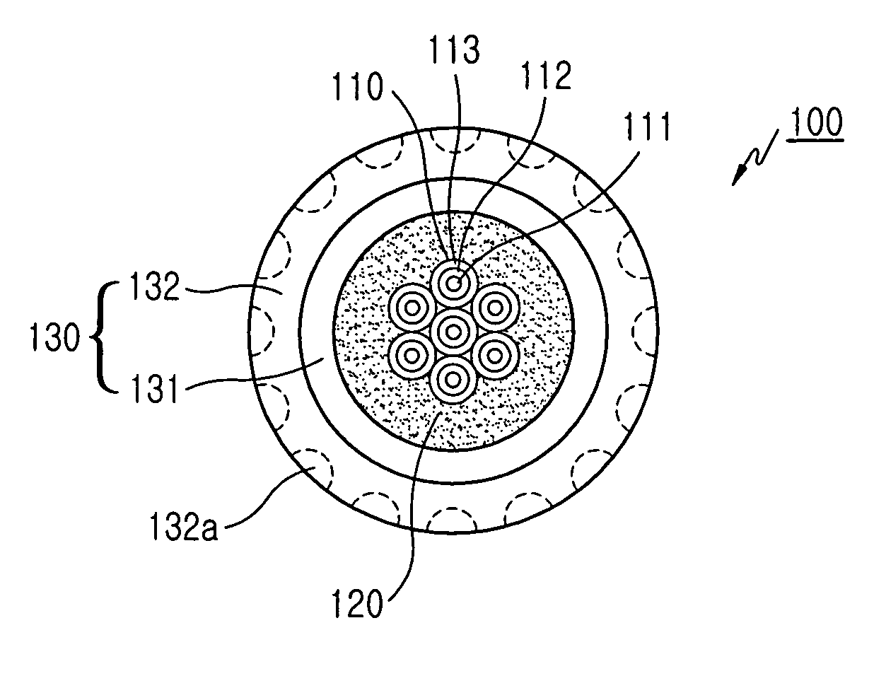
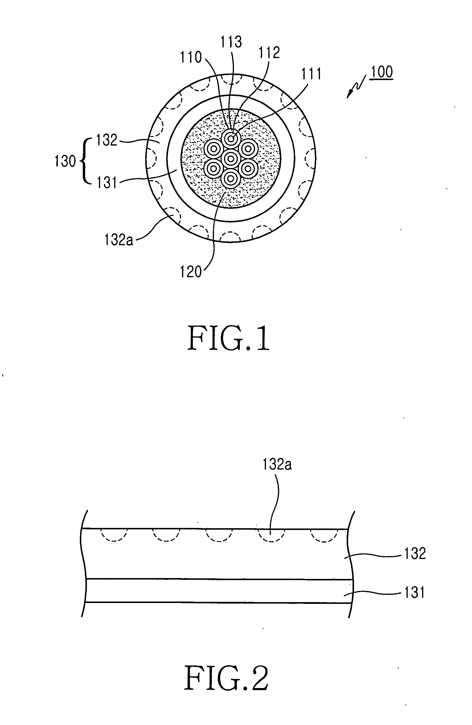
[0020]FIG. 1 is a diagram showing an optical fiber cable 100 including an external sheath having a multi-layer structure including a second layer formed with a crater according to the present invention. The optical fiber cable 100 includes at least one optical fiber 110, an external sheath 130 binding optical fibers 110 together, and a waterproof member 120 for preventing moisture from penetrating into the optical fibers 110.

[0021] Each of the optical fibers 110 includes a core 111, which is an optical signal transmission medium, a clad 112 surrounding an outer surface of the core 111, and a coating layer 113 coated at an outer surface of the clad 112. In addition, each of optical fibers 110 further includes a colored layer for identifying the optical fibers by coating a specific color on the outer surface of the coating layer 113.

[0022] The core 111 includes a material capable of transmitting the optical signal. The core 111 is surrounded by the clad 112, which has a refractive in...

second embodiment

[0027]FIG. 4 is a diagram showing an optical fiber cable 200 including an external sheath structure having a multi-layer structure formed with a ribbon optical fiber according to the present invention. The optical fiber cable 200 includes at least one ribbon optical fiber 210, an external sheath 240 for binding the ribbon optical fibers 210 together, and a waterproof member 250 formed between the external sheath 240 and the ribbon optical fibers 210.

[0028] Each of ribbon optical fibers 210 includes a plurality of optical fibers 230 aligned in line with each other and a ribbon coating layer 220 surrounding an outer surfaces of the optical fibers 230 in order to bind optical fibers 230 together. Also, each of the optical fibers 230 includes a core 231, which is an optical signal transmission medium, a clad 232 surrounding the core 231, and a coating layer 233 surrounding an outer surface of the clad 232.

[0029] Predetermined colors may be coated to the ribbon coating layer 220 in orde...


PUM


Abstract

An optical fiber cable and a method of fabricating the same are disclosed. The optical fiber cable includes at least one optical fiber including a core, which is an optical signal transmission medium, a clad surrounding an outer peripheral surface of the core, and a coating layer surrounding an outer peripheral surface of the clad. The optical fiber cable also includes an external sheath including a first layer having a predetermined thickness and a second layer made of polymer material and formed at an outer peripheral surface of the first layer through an extruding process and a waterproof member accommodated between the external sheath and the optical fibers. A plurality of recesses having a predetermined depth and a predetermined diameter are formed on the second layer.

Description

CLAIM OF PRIORITY [0001] This application claims priority to an application entitled “Optical fiber cable and method of manufacturing the same,” filed in the Korean Intellectual Property Office on Nov. 27, 2003 and assigned Serial No. 2003-85069, the contents of which are hereby incorporated by reference. BACKGROUND OF THE INVENTION [0002] 1. Field of the invention [0003] The present invention relates to an optical fiber cable, and more particularly to an optical fiber cable, installed using air pressure, and including an external sheath having a multi-layer structure. [0004] 2. Description of the Related Art [0005] Conventional optical fibers includes a core made of glass material or plastic material having a high refractive index at a center portion thereof, a clad surrounding an outer surface of the core and having a refractive index lower than that of the core, and a coating layer coated on an outer surface of the clad in order to protect the core and the clad. [0006] Such optic...

Claims


Application Information

Patent Timeline
Patent Type & Authority Applications(United States)
IPC IPC(8): G02B6/44G02B6/46
CPCG02B6/4438G02B6/4403G02B6/4405G02B6/443G02B6/44384
Inventor LEE, HO-SOONHWANG, JOONG-JINPARK, KYUNG-TAEKANG, HEE-GOO
Owner SAMSUNG ELECTRONICS CO LTD
Why Eureka
Try Eureka