Shunt and access port

a technology of access port and shunt, which is applied in the field of cerebrospinal fluid, can solve the problems of shunts being prone to failure, serious injury and even death,

Inactive Publication Date: 2005-06-02
MURPHY KIERAN P +2
View PDF5 Cites 17 Cited by
  • Summary
  • Abstract
  • Description
  • Claims
  • Application Information

AI Technical Summary

Benefits of technology

The present invention provides a CSF shunt and an access port that overcome or minimize the shortcomings of previous designs.

Problems solved by technology

The technical problem addressed in this patent text is the high incidence of complications and failure of prior art cerebrospinal fluid shunts, including infection, obstruction, disconnection, under draining, and over draining, which can lead to serious injury and even death. The current shunts are also prone to failure, often requiring complete replacement. The patent text discusses various attempts to overcome these issues, such as the use of telemetry, but the shunts still face the same challenges. The patent seeks to provide a solution to address these complications and failures of prior art shunts.

Method used


Image

  • Shunt and access port
  • Shunt and access port
  • Shunt and access port

Examples


Embodiment Construction

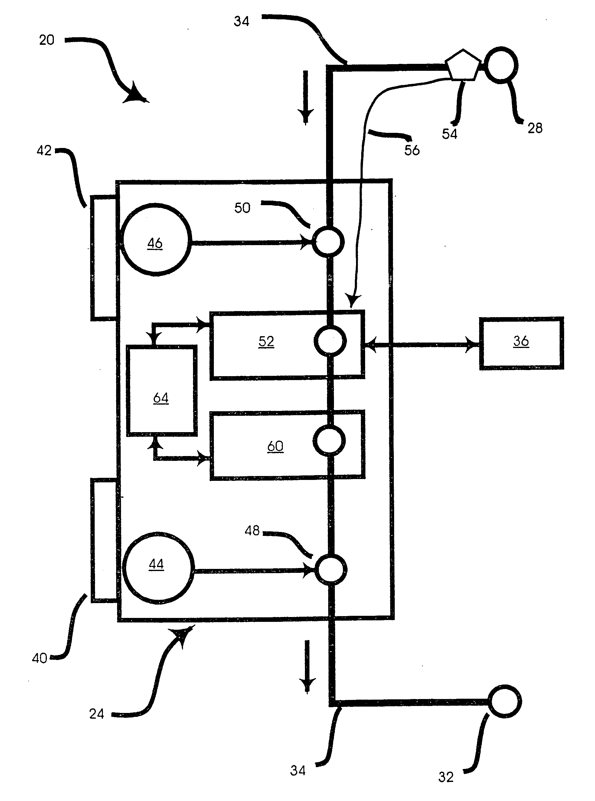
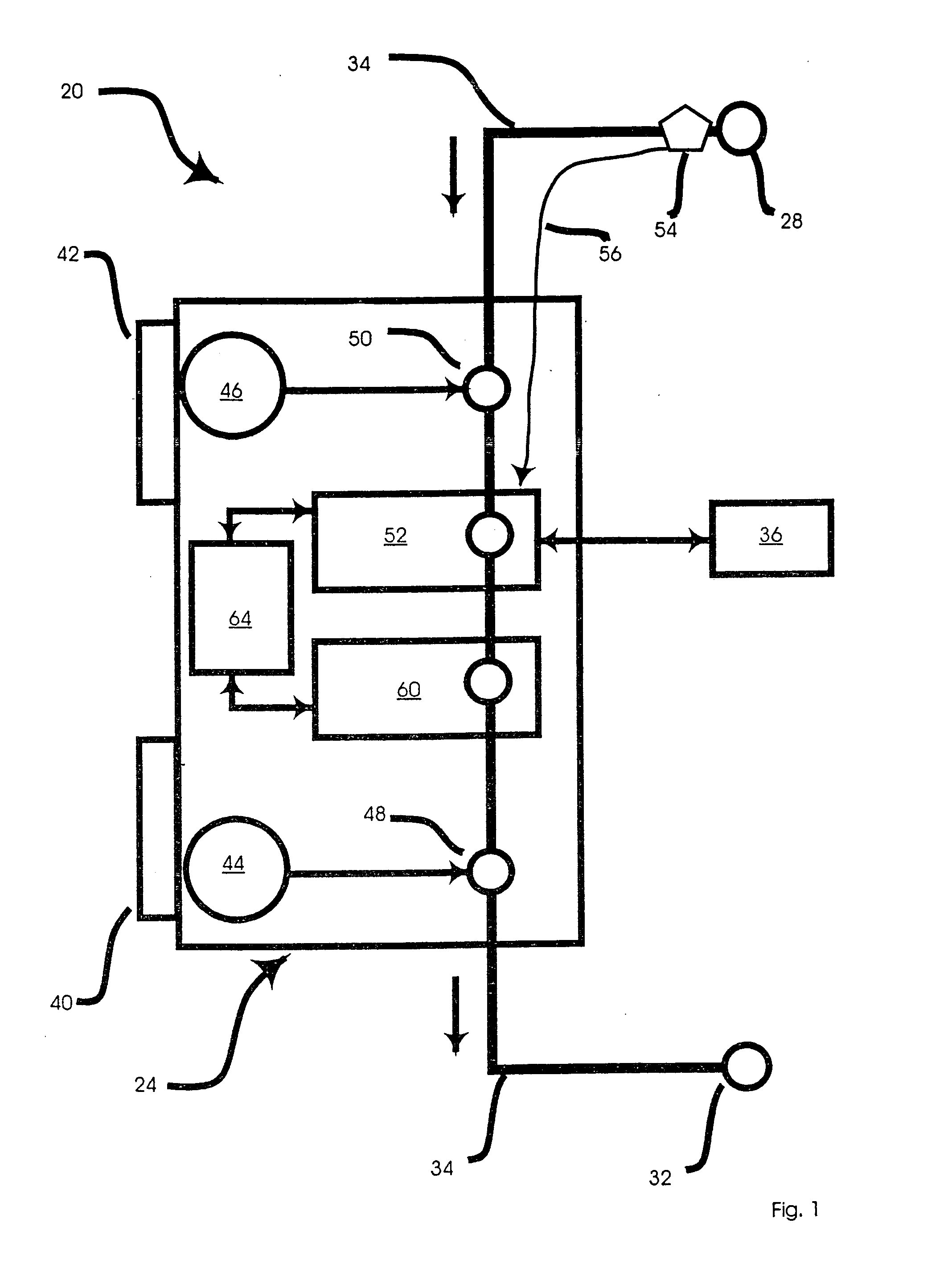
[0074] Referring now to FIG. 1, a schematic representation of a CSF shunt is indicated generally at 20. Shunt 20 comprises a master control unit 24 (which can also be referred to as the active component) that interconnects a first catheter 28, and a second catheter 32 via a catheter line 34. Master control unit 24 is preferably minitiarized and made of a biocompatible material such that it can be safely inserted in the patient's abdomen, either intra-peritoneal or extra-peritoneal, using a standard abdominal incision, and remain therein as needed to drain CSF.

[0075] After master control unit 24 is inserted into the patient's abdomen, first catheter 28 can then be tunneled from the abdomen rostrally (or caudaly) into a CSF space in the scalp to serve as an inlet for excess CSF, which in a present embodiment is a ventricle. (As used herein, the term CSF space includes any space in the body that can generate an excess of CSF requiring drainage.) A small incision in the scalp can then ...


PUM


Abstract

A shunt for draining cerebral spinal fluid from the brain and an access port for use therein is provided. In an embodiment, the shunt includes a master control unit that is located in the abdomen, which interconnects a ventricular catheter and a second catheter, typically located in the peritoneal cavity. In a specific embodiment, the master control unit includes a variety of ‘smart’ features including at least one access port to allow the injection of solutions for the prevention or removal of blockages in the catheter, and/or antibiotics. The access port can have other uses, such as allowing a point of access for physical navigation of a catheter or the like within the shunt, thereby providing another option for breaking-up blockages, and/or allowing an access point for repairing the shunt's components. Additionally, the master control unit includes a diagnostic unit that transmits, either wirelessly or through a wired connection via the access port, diagnostic information about the status of the patient and/or the shunt.

Description


Claims


Application Information

Patent Timeline
Owner MURPHY KIERAN P
Why Eureka
Try Eureka