Stent delivery system

a technology of stent and stent body, which is applied in the field of medical devices, can solve the problems of unfavorable repositioning of stent, unsafe repositioning of stent, and inability to safely place stent back within the sheath, so as to prevent undesired forward movement of the tip, accurate stent position, and minimize the effect of undesired movement of sten

Inactive Publication Date: 2005-06-02
INTEK TECH
View PDF25 Cites 28 Cited by
  • Summary
  • Abstract
  • Description
  • Claims
  • Application Information

AI Technical Summary

Benefits of technology

[0021] Simultaneous opposite motions of the distal sheath portion in the distal direction and the proximal sheath portion in the proximal direction tend to balance each other thereby preventing undesired forward movement of the tip of the catheter and stent during deployment which can occur with prior art systems, especially when used to introduce stents through tortuous vascular passages. When using prior art delivery systems for self-expanding stents, once the distal portion of the stent is exposed it expands in a flared configuration and the distal end of the stent can touch or come close to the vessel wall. At that stage it is unsafe to try to reposition the stent. In addition, the stent cannot be safely placed back within the sheath once a few millimeters of the stent is exposed, and expands, outside the sheath. When undesired forward motion of the distal end of the catheter occurs in prior art delivery systems the stent must be deployed even if it is not in desired delivery location since further repositioning of the stent is impossible. The present invention avoids this problem since undesired movement of the stent is minimized due to the movement of the proximal and distal sheath portions in opposite directions. Further, since the partially exposed stent is still held at both ends, it can be safely repositioned into the specific desired delivery location prior to its complete deployment.
[0022] Finally, since the mid-region of the stent is exposed prior to the exposure and release of the end regions of the stent, the spring effect, and jumping of the stent caused by the spring effect, is eliminated.
[0024] According to a third aspect of the invention a stent delivery system includes an outer tubular member, an inner tubular member, a stent arranged between the inner tubular member and the outer tubular member, and an inflatable balloon coupled to a tip of the catheter, the balloon being distally arranged relative to the stent and to the distal end of the outer tubular member. During stent delivery, the system is initially positioned with the stent situated at the desired treatment site in a conventional manner. The balloon is then inflated via a balloon lumen until the surface of the balloon wall is placed in abutment with the wall of the vessel to effectively lock the delivery system in place in the vessel thereby eliminating the possibility of any undesired movement of the system during stent deployment. After the balloon is inflated, the outer tubular member is retracted to thereby release the stent. Since the system is effectively locked in place by the engagement of the inflated balloon with the vessel wall, inadvertent movement of the system during the deployment of the stent is eliminated and accurate placement of the stent is promoted.

Problems solved by technology

At that stage it is unsafe to try to reposition the stent.
In addition, the stent cannot be safely placed back within the sheath once a few millimeters of the stent is exposed, and expands, outside the sheath.
When undesired forward motion of the distal end of the catheter occurs in prior art delivery systems the stent must be deployed even if it is not in desired delivery location since further repositioning of the stent is impossible.

Method used


Image

  • Stent delivery system
  • Stent delivery system
  • Stent delivery system

Examples


Embodiment Construction

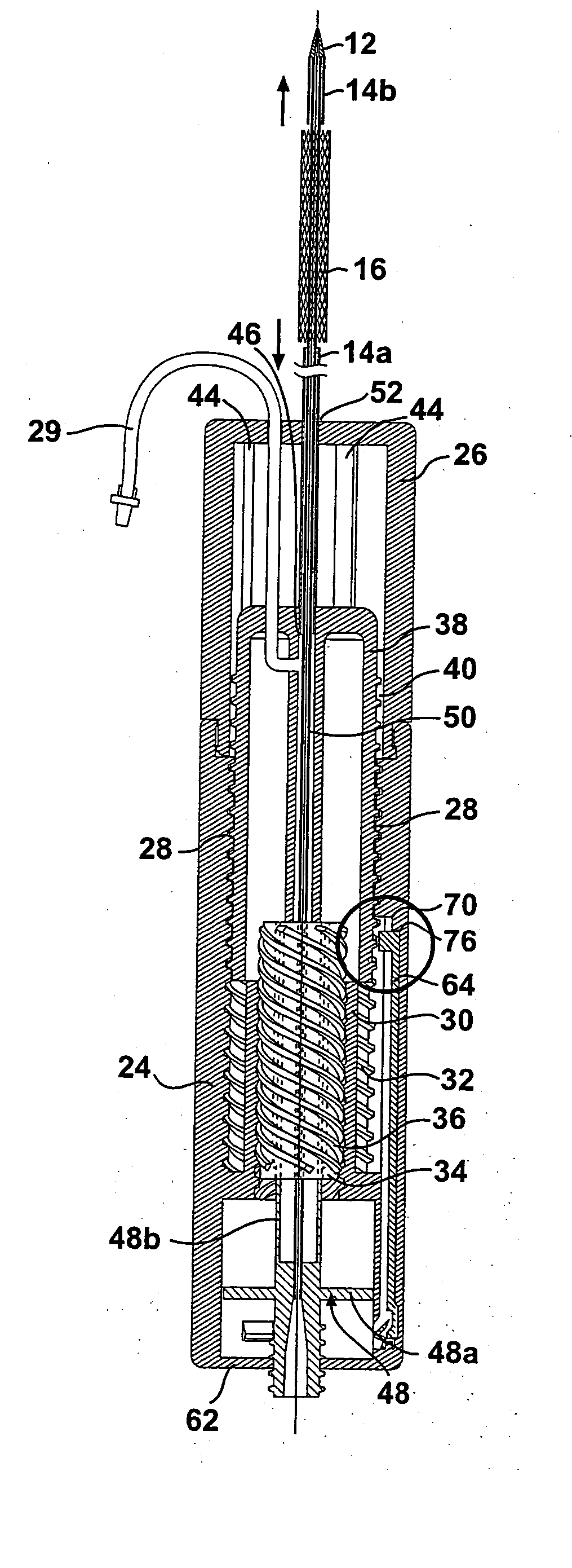
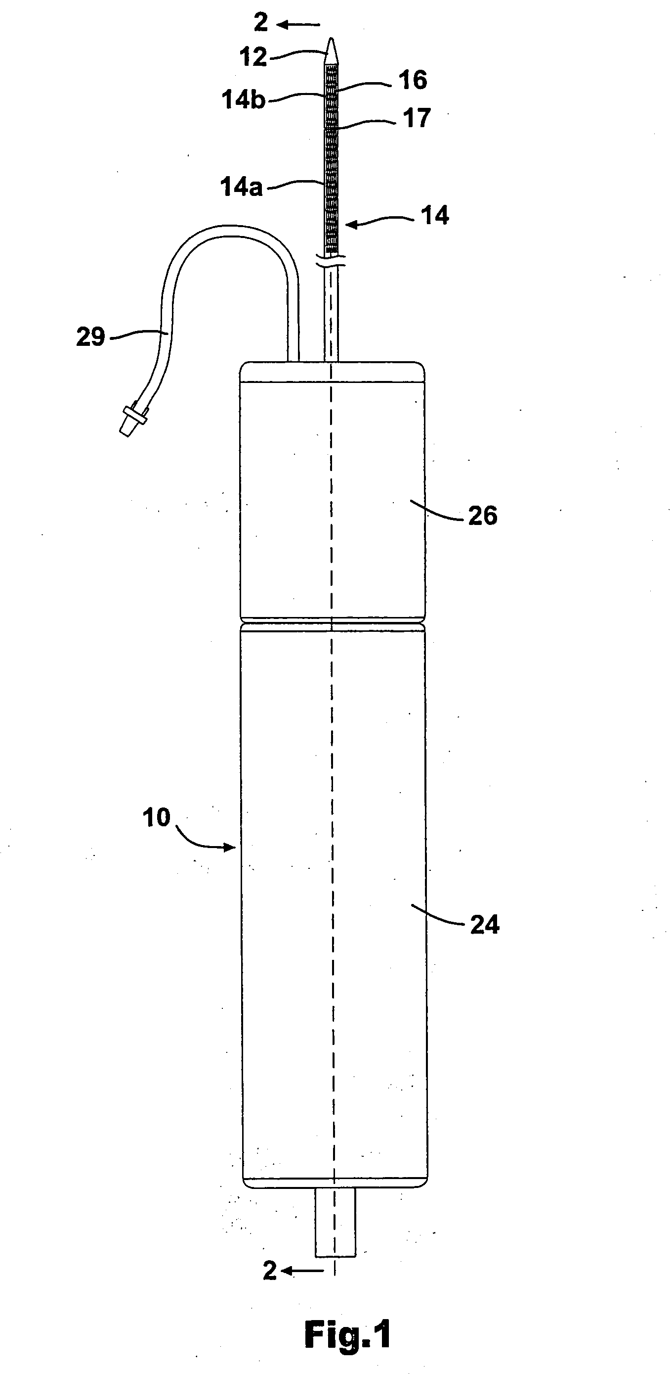
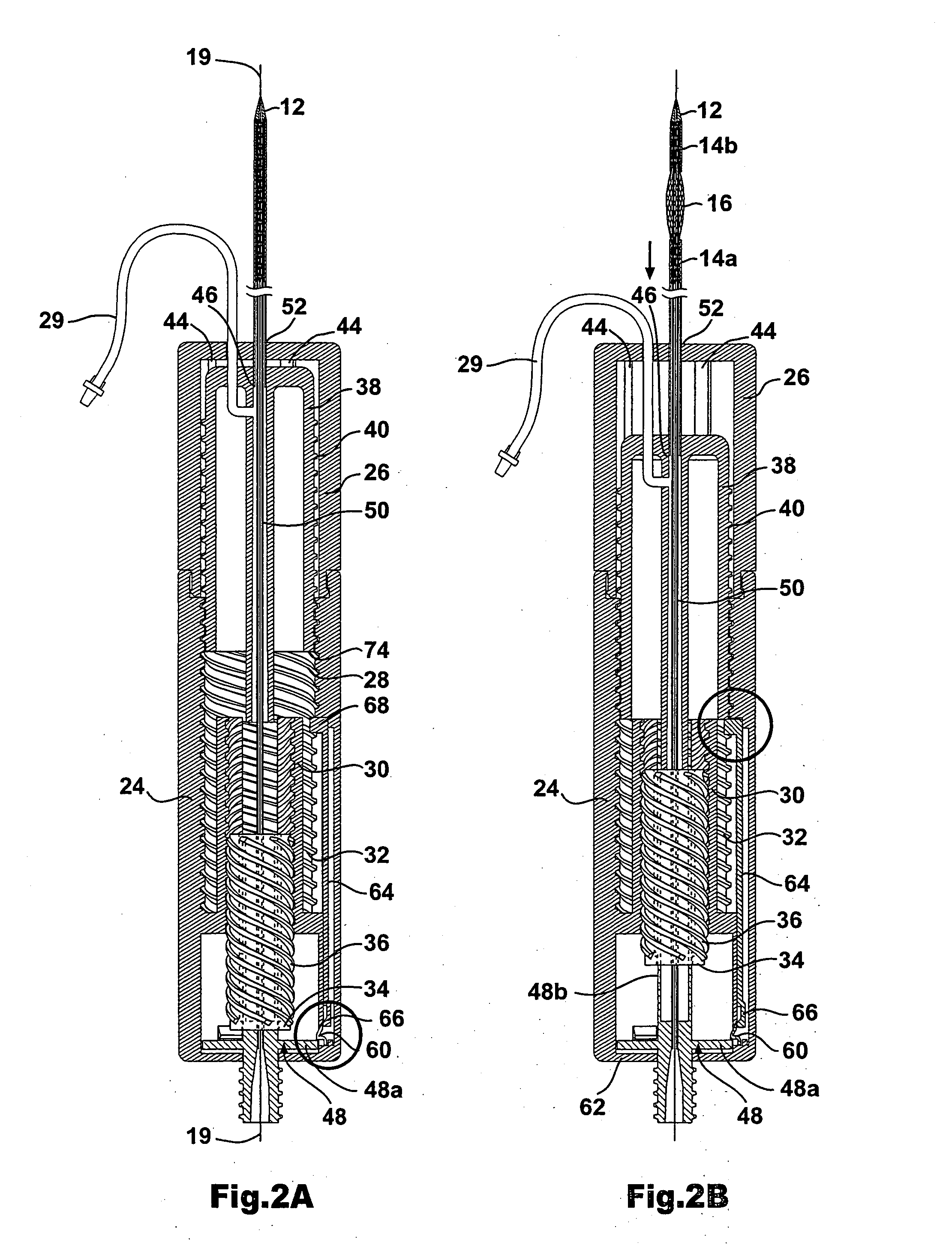
[0038] As shown in FIG. 1, the stent delivery system according to the present invention includes a a sheath assembly 14 for retaining a self-expanding stent 16 at a distal end of the system, the sheath assembly 14 including a proximal sheath portion 14a and a distal sheath portion 14b. The stent delivery system further includes a mechanism 10 for controlling the movement of the proximal sheath portion 14 in a proximal direction and the movement of the distal sheath portion 14b in a distal direction. The proximal sheath portion 14a and the distal sheath portion 14b are operably coupled to the mechanism 10 such that proximal sheath 14a and distal sheath portion 14b can be moved apart by the physician in a controlled manner, by operation of the mechanism 10, to thereby expose and deploy the self expanding stent 16. The details regarding the operative connection between the proximal sheath portion 14a and the mechanism 10, as well as the operative connection between the distal sheath po...


PUM


Abstract

A first stent delivery system provided with a sheath for covering the stent, the sheath including proximal sheath portion adapted to be movable in a proximal direction and a distal sheath portion adapted to be moveable in a distal direction. A second stent delivery system including an outer and intermediate tubular members covering a chamber with a preloaded stent, the outer tubular member being retractable prior to the retraction of the intermediate sheath and release of the stent. A third stent delivery system including with an inflatable balloon at a distal end of the system for fixing the system in place within the vessel prior to the release of the stent thereby insure accurate stent deployment.

Description

FIELD OF THE INVENTION [0001] This invention relates generally to medical devices, and more particularly to a system for delivering stents of the self-expanding type to a desired location in a vessel to be treated. BACKGROUND OF THE INVENTION [0002] A stent is a generally longitudinal cylindrical device formed of biocompatible material, such as metal or plastic, which is used in the treatment of stenosis, strictures, or aneurysms in body blood vessels and other tubular body structures, such as the esophagus, bile ducts, urinary tract, intestines or the tracheo-bronchial tree. [0003] A stent is held in a reduced diameter unexpanded configuration within a low profile catheter until delivered to the desired location in the tubular structure, most commonly a blood vessel, whereupon the stent radially expands to an expanded diameter configuration in the larger diameter vessel to hold the vessel open. Radial expansion may be accomplished by manually inflating a balloon which is attached t...

Claims


Application Information

Patent Timeline
Patent Type & Authority Applications(United States)
IPC IPC(8): A61F2/06A61F2/84
CPCA61F2/95A61F2/958A61F2002/9583A61F2/97A61F2002/9517A61F2/966A61F2/9517A61F2/9662
Inventor RABKIN, DMITRYMORAG, EYALPERELSON, OPHIRHADAR, YORAM
Owner INTEK TECH
Why Eureka
Try Eureka