Glass run for vehicle

a technology for vehicles and glass runs, applied in the field of vehicle glass runs, can solve the problems of poor productivity, complicated molding work, and inability to move well, and achieve the effects of reducing sliding resistance, reducing sliding resistance, and reducing the difference in level

Inactive Publication Date: 2005-06-09
TOYODA GOSEI CO LTD
View PDF17 Cites 37 Cited by
  • Summary
  • Abstract
  • Description
  • Claims
  • Application Information

AI Technical Summary

Benefits of technology

[0047] Further, in the interior seal lip, when the door glass is inserted in the glass run body, the interior extension lip contacts at the front end the boundary part between the bottom projection and the inside of the interior side wall, so that the interior seal lip securely holds the front end of the interior extension lip, and the triangular false hollow part can be formed by the interior seal lip, the interior extension lip and the interior side wall to elastically absorb vibration of the door glass, push the door glass outside of the vehicle, and reduce difference in level between the door glass and the door frame.
[0048] The invention provides the interior seal lip of the glass run with the body of the interior seal lip, the bent portion thereof and the front end portion of the same, and performs the treatment on the contact face of the interior side wall for reducing the sliding resistance, so that the interior side wall can exactly hold the door glass even when it stops halfway of the door frame, and at the same time, for reducing the sliding resistance, so that the door glass can smoothly move vertically.
[0049] The present invention bends and extends the interior extension lip from the front end of the interior seal lip toward the interior side wall, and since the interior extension lip is formed to be curved in convex toward the interior side wall, when the door glass is inserted into the inside of the glass run body, the invention may forms the almost triangular false hollow part, and since the interior extension lip is formed to be curved in convex toward the interior side wall, when the door glass pushes the interior seal lip, the interior extension lip can be easily bent to absorb vibration of the door glass.
[0050] The interior extension lip is supported at the front end by the bottom wall so as to hold the almost triangular false hollow part formed by the interior seal lip, the interior extension lip and the interior side wall. Thus, the door glass can be steadily held and absorb vibration of the door glass.
[0051] The present invention respectively bends and extends the exterior extension lip and the interior extension lip from the front ends of the exterior seal lip and of the interior seal lip toward the exterior side wall and the interior side wall. The exterior extension lip and the interior extension lip are formed to be curved in convex toward the exterior side wall and the interior side wall, and therefore, when the door glass is inserted in the inside of the glass run body, the exterior seal lip, the exterior extension lip, and the exterior side wall form the almost triangular false hollow part, and similarly, the interior seal lip, the interior extension lip and the interior side wall can form the triangular false hollow part. Thus, these triangular false hollow parts can hold the door glass securely and elastically at the front ends of the exterior seal lip and the interior seal lip.
[0052] Since the exterior extension lip and the interior extension lip are respectively curved in convex toward the exterior side wall and the interior side wall, when the door glass pushes the exterior seal lip and the interior seal lip, the exterior extension lip and the interior extension lip can be easily bent to absorb vibration of

Problems solved by technology

However, if making thick, resistance of the door glass 5 moving vertically becomes large so that the movement does not work well.
However, in case of molding the hollow seal lips by extrusion forming, for preventing the hollow parts from being crushed owing to negative pressure when carrying out the extrusion forming, it has been necessary to continuously control an air at predetermined pressure and send it to the hollow parts, so that the molding work has been complicated to lower the rate of molding, and the productivity has not been good.

Method used


Image

  • Glass run for vehicle
  • Glass run for vehicle
  • Glass run for vehicle

Examples


first embodiment

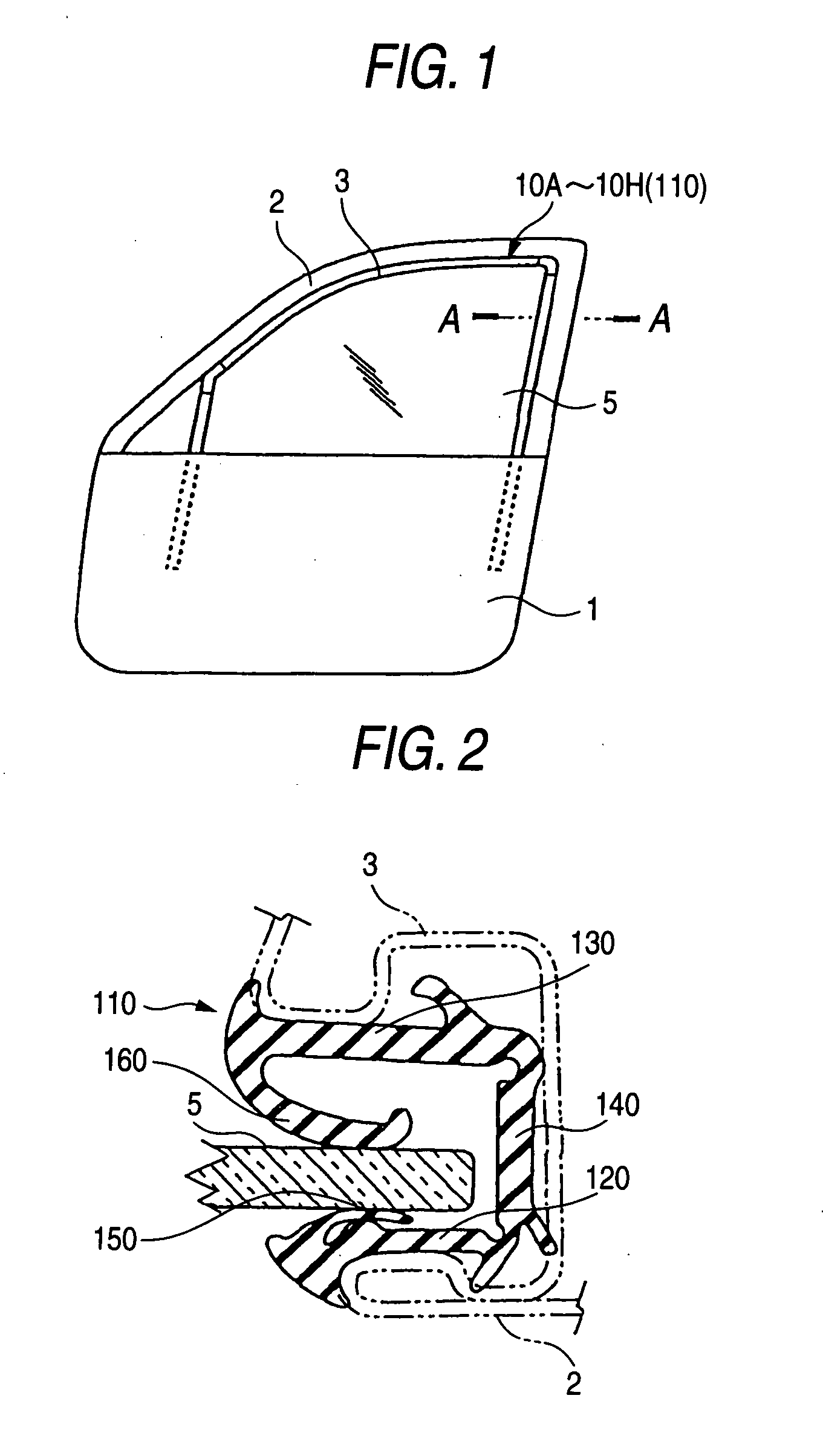
[0071] Explanation will be made to a first embodiment of the invention on the basis of FIGS. 1,3 through 6. FIG. 1 is a side view of the vehicle door. As shown in the same, the vehicle door 1 is attached with the door frame 2 at its upper part for moving vertically the door glass 5. That is, in the inner circumference of the door frame 2, a channel 3 is provided for attaching the glass run 10A so as to guide the door glass 5 moving vertically as well as seal the door glass 5 and the door frame 2.

[0072] The glass run 10A comprises an almost linear part formed by an extrusion forming and apart formed by molding for connecting the extruded part. The extruded part comprises a part to be attached to the upper part of the door frame 2, a part to be attached to a rear and vertical side of the door frame 2, and a part to be attached to a front and vertical side of the door frame 2. The molded parts connect these extruded parts in shape corresponding to the door frame 2 to be the parts atta...

second embodiment

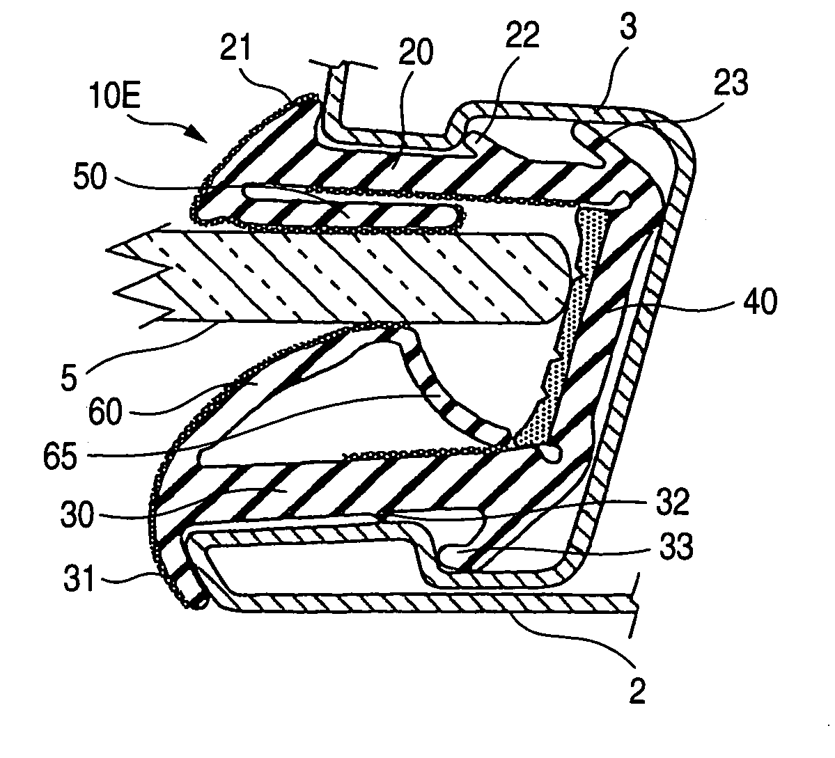
[0087] Next, explanation will be made to a second embodiment on the basis of FIGS. 4 and 6. FIG. 6 is a cross sectional view along A-A line of FIG. 1 when attaching the glass run 10B to the channel 3 of the door frame 2. The second embodiment is different from the first embodiment in the contact face 32 of the vehicle-interior side wall 30 of the glass run 10B and the vehicle-interior seal lip body 61, and is similar in other parts. Therefore, explanations for the other parts than the contact face 32 and the vehicle-interior seal lip body 61 will be omitted. The contact face 32 is provided with a projection 33 of the vehicle-interior side wall in a vicinity of central part inside of the vehicle-interior side wall 30. There is a curved surface like an arc-shape in cross section formed to be continuous from the projection 33 to the bottom wall 40.

[0088] Therefore, the front end portion 63 of the vehicle-interior seal lip has a length of contacting the slope of the projection 33 of th...

third embodiment

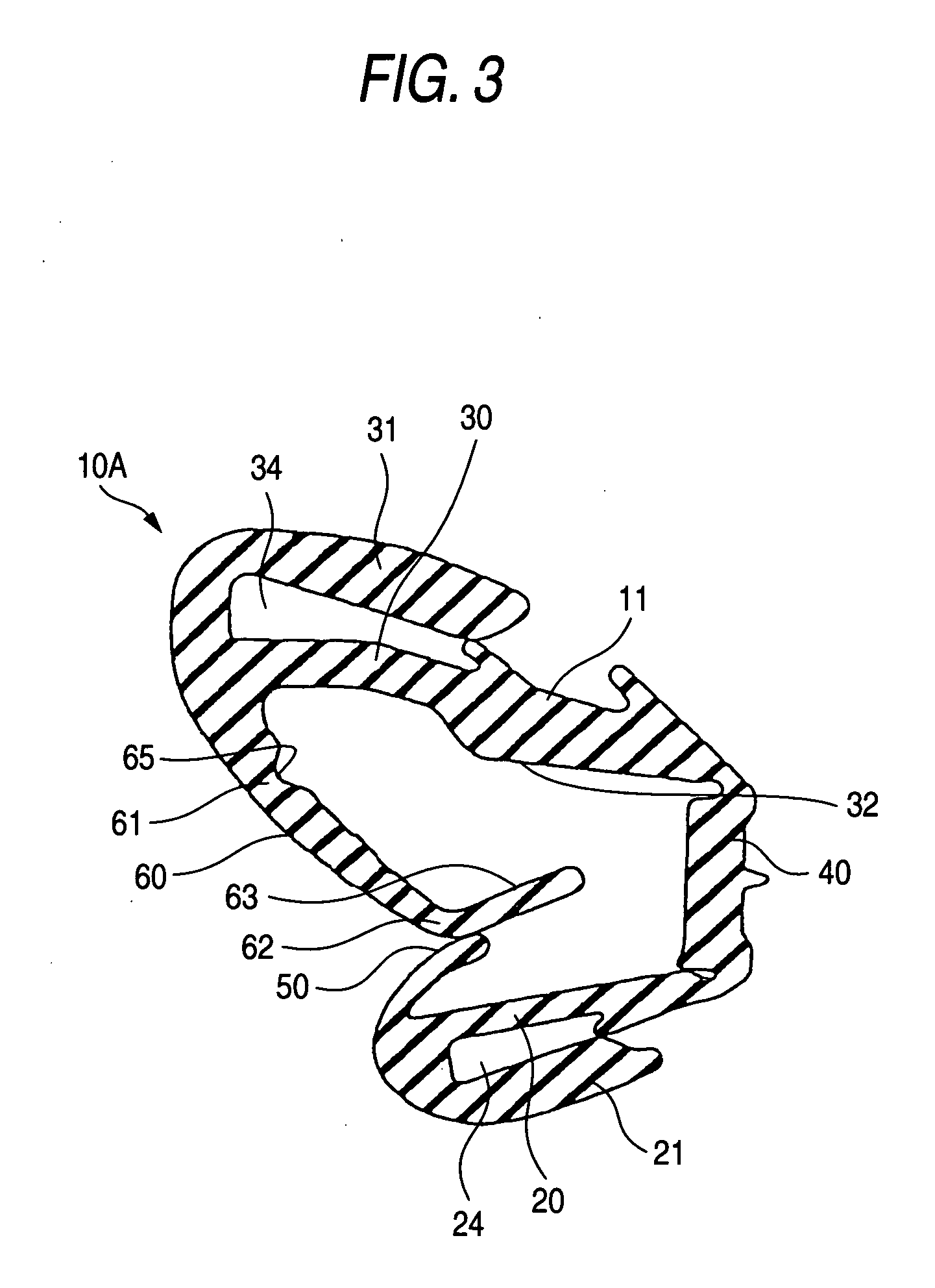
[0093] A third embodiment will be explained on the basis of FIGS. 7 and 9.

[0094] A cross sectional shape of an extruded part to be attached to a vertical side of the door frame 2 is shown in FIG. 7.

[0095] The vehicle-interior seal lip 60 extends from the vicinity of the front end of the vehicle-interior side wall 30 toward the inside of the U-shape in cross section of the glass run body 11. A vehicle-interior cover lip 31 extends in the vehicle-interior direction at the front end of the side wall 30.

[0096] The vehicle-exterior seal lip 50 extends from the front end of the vehicle-exterior side wall 20 toward the inside of the U-shape in cross section of the glass run body 11. A vehicle-exterior cover lip 21 extends in the vehicle-exterior direction at the front end of the vehicle-exterior side wall 20.

[0097] As shown in FIG. 9, when attaching the glass run 10C to the channel 3 of the door frame 2, the vehicle-interior side wall of the channel 3 is inserted in a groove 34 of the ...


PUM


Abstract

The invention is to provide a vehicle glass run, in which a seal lip prevents displacement or vibration of a door glass, exactly holds the door glass, reduces sliding resistance between the door glass and the seal lip, and prevent generation of abnormal noises. The vehicle-interior seal lip is formed to be longer than a vehicle-exterior seal lip, and has a body of the vehicle-interior seal lip extending from the vehicle-interior side wall, a bent portion thereof being bent toward a bottom wall from the body of the vehicle-interior seal lip, and a front end portion of the same extending from the bent portion with a length contacting the vehicle-interior side wall at the front end portion of the vehicle-interior seal lip, when the door glass contacts the vehicle-interior seal lip. The vehicle-interior side wall is performed with a treatment to reduce the sliding resistance on a face of the vehicle-interior side wall contacted by the vehicle-interior seal lip.

Description

BACKGROUND OF THE INVENTION [0001] 1. Field of the Invention [0002] The present invention relates to a vehicle glass run which is mounted in the inner circumference of a door frame of a vehicle door for guiding a door glass moving up and down as well as sealing the space between the door frame and the door glass. [0003] 2. Description of Related Art [0004] As shown in FIG. 1, in the inner circumference of the door frame 2 of the vehicle door 1, the glass run 110 is attached for guiding the door glass 5 moving up and down. The cross sectional structure of an existing glass run is shown in FIG. 2 which is a cross sectional view seeing from A-A line of FIG. 1. [0005] By the way, FIGS. 1 and 2 show a door of a sash-type, and this glass run may be also applied to doors of press type. [0006] Conventionally, the glass run 110 has been, as shown in FIG. 1, attached in a channel 3 of the door frame 2 for guiding the door glass 5 moving up and down as well as sealing the space between the doo...

Claims


Application Information

Patent Timeline
Patent Type & Authority Applications(United States)
IPC IPC(8): B60J10/04F16J15/02F16J15/06
CPCB60J10/006B60J10/0094F16J15/061F16J15/025B60J10/042B60J10/277B60J10/50B60J10/76
Inventor TAKASE, TOMOHIROOMORI, HITOSHIARITAKE, MASANORIHAMABATA, MITSUOKOGISO, HARUMIITO, AKIRA
Owner TOYODA GOSEI CO LTD
Why Eureka
Try Eureka