Valve for use with chest drainage system

a valve and chest technology, applied in the field of valves, can solve the problems of abnormal positive pressure in the pleural space and can be very dangerous

Active Publication Date: 2005-06-09
ATRIUM MEDICAL
View PDF6 Cites 5 Cited by
  • Summary
  • Abstract
  • Description
  • Claims
  • Application Information

AI Technical Summary

Benefits of technology

[0009] A valve according to the present invention includes first and second sealing surfaces that are opposed so that air is allowed to flow from an upstream to a downstream location through the first and second sealing surfaces. Air is prevented from moving from the downstream location to the upstream location when the first and second sealing surfaces are in contact. The valve element allows air to move from the downstream chamber to the upstream chamber when a certain pressure differential is achieved. Specifically, the valve according to one embodiment of the present invention also includes a pressure relief actuating element disposed in the valve and located adjacent the valve element. When a predetermined pressure differential between the upstream side and the downstream side is reached, the valve element deforms and contacts the pressure relief actuating element so that the element causes the first and second sealing surfaces to separate and reduce the pressure differential between the upstream side and the downstream side. The valve according to an embodiment of the invention also includes reinforcing portions along at least a portion of the length of the valve. The reinforcing portions provide additional rigidity to the valve when the pressure in the upstream location is lower than the pressure in the downstream location and allows the sealing elements to be flexible so that the sealing elements open at slight pressure differentials when pressure in the upstream location is higher than the pressure in the downstream location.
[0011] A valve constructed according to an embodiment of the invention prevents reverse flow under certain conditions. Specifically, when the pressure difference between the upstream side and downstream side is within a predetermined limit, i.e., the downstream side has a higher pressure than the upstream side, the valve will prevent reverse flow. Accordingly, the valve operates as a one-way valve and opens when the pressure difference between the upstream side and the downstream side is positive and prevents reverse flow when the pressure difference between the upstream and the downstream is negative. In certain conditions the valve will allow the flow from the “downstream” side to the “upstream” side to relieve a pressure difference between the two sides of the valve. Specifically, if the pressure differential between the upstream side and the downstream side is above a predetermined limit, the valve will operate to reduce the pressure difference between the upstream and downstream locations. In such a condition, the valve opens and allows higher pressure air into the upstream chamber so that the pressure is increased to a relieve the pressure in the upstream chamber.

Problems solved by technology

Since the physiologically normal pressure of the pleural space is between −3 and −8 cm of water, any positive pressure within the pleural space is abnormal and can be very dangerous.
If the pressure in the lung cavity falls below a predetermined minimum (i.e., excessive sub-atmospheric pressure) lung tissue can be damaged and sutures could become dislodged which could lead to bleeding.
The design of the one-way valve for use in a chest drainage device poses engineering challenges because the valve should open at a very slight pressure difference between the upstream side and the downstream side of the valve.

Method used


Image

  • Valve for use with chest drainage system
  • Valve for use with chest drainage system
  • Valve for use with chest drainage system

Examples


Embodiment Construction

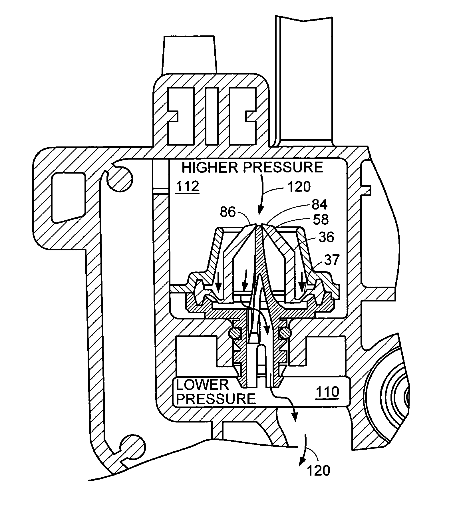
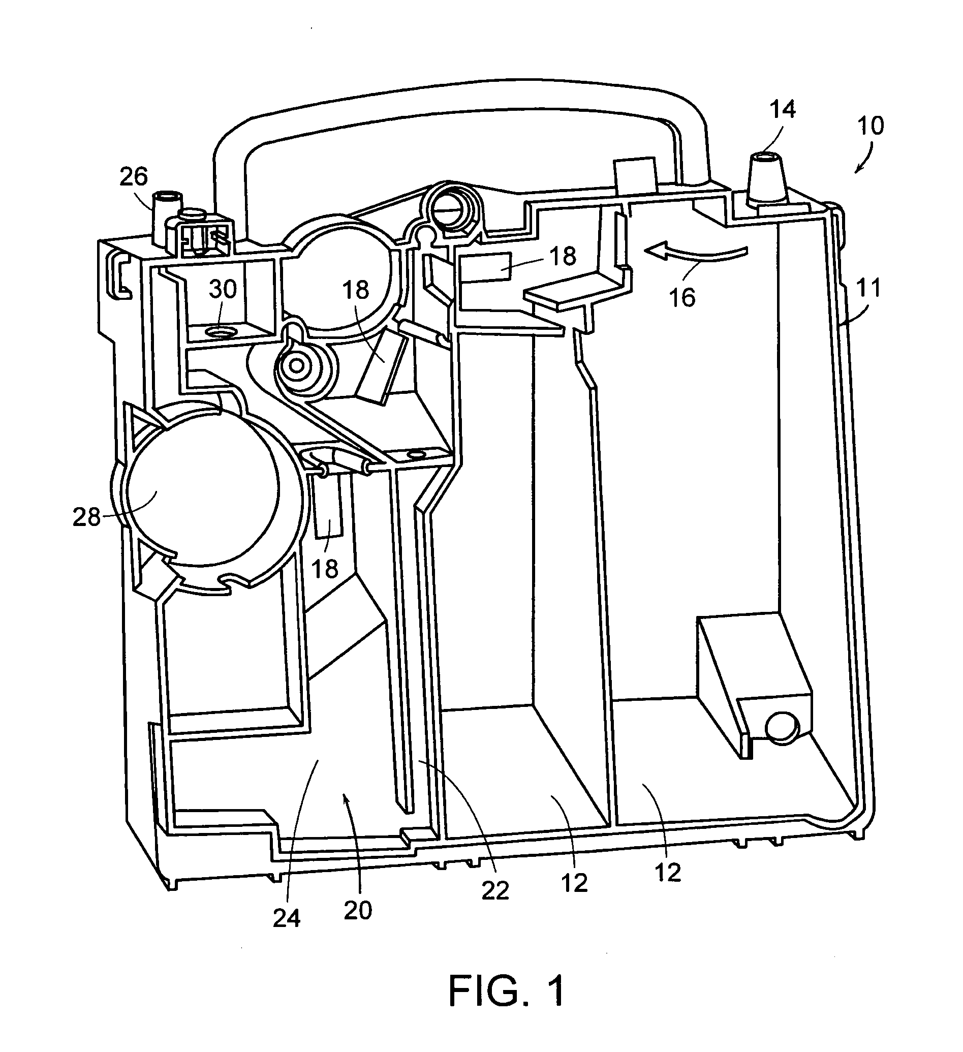
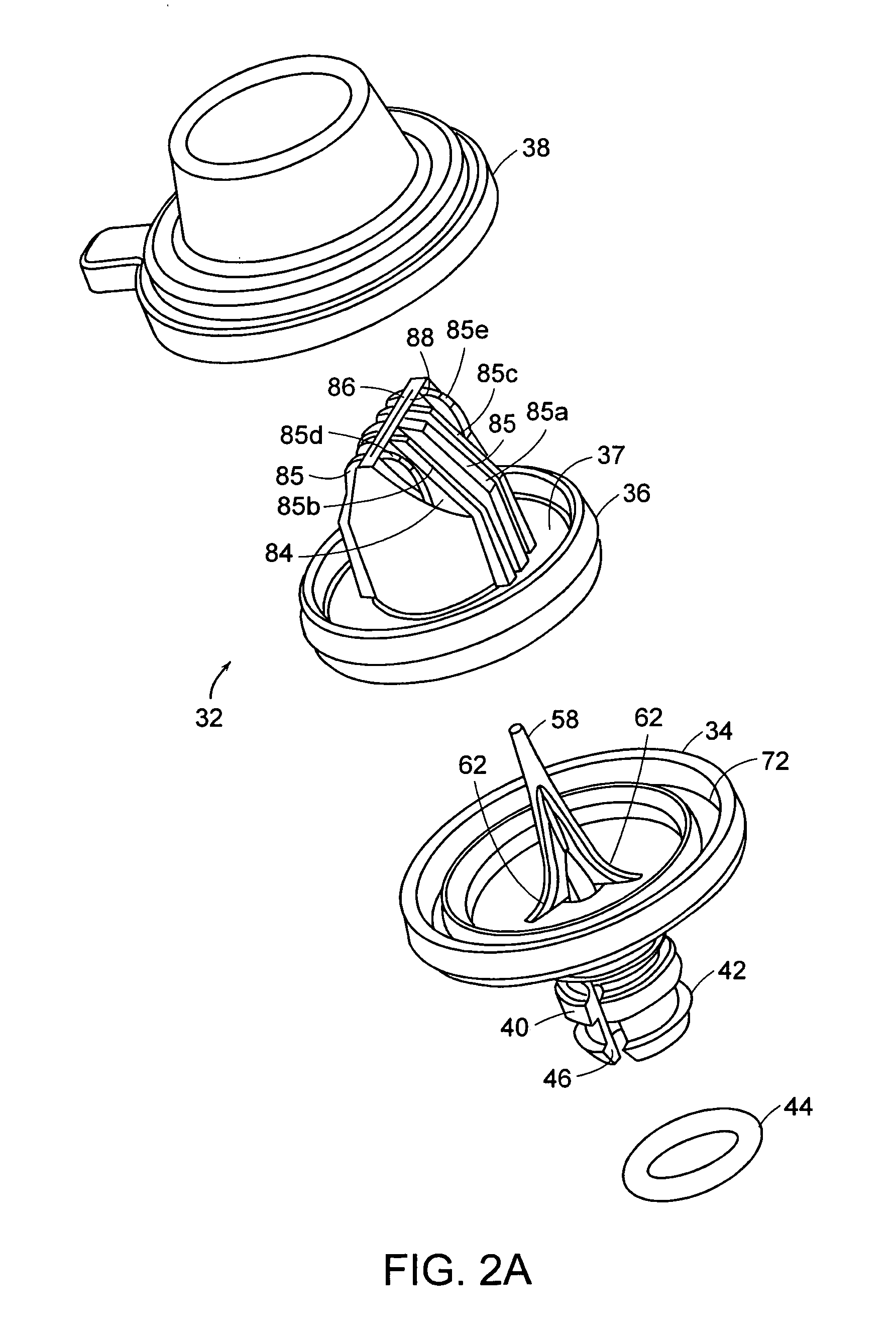
[0024] The description of the inventive valve is in the context of a chest drainage device. Of course, the valve may be used in other medical and non-medical fields which require similar functionality. As used in this application the term “pressure” refers to gauge pressure, that is ambient air pressure will be at 0.0 cm of water. Pressure above ambient air pressure will be positive and pressures below ambient are negative. Pressure differences are generally referred to as positive pressure differences when going from the upstream side to the downstream side, unless otherwise indicated. That is, a positive pressure difference of, for example, 2 cm of water will open the valve and allow air to flow from the upstream side to the downstream side. A negative pressure difference could occur if the downstream side has a higher pressure than the upstream location. As an example, a downstream pressure of atmospheric pressure and a −8 cm of water pressure in the upstream location would be te...


PUM


Abstract

A valve for use in a chest drainage device is disclosed, the chest drainage device is adapted to receive liquid and air from a patient's chest cavity via an inlet and to permit air to escape through an outlet for air to leave the chest drain, the inlet and outlet define a flow path and the valve is disposed along the flow path. The valve has a valve element that separates an upstream chamber from a downstream chamber and has a first and second sealing surface that are opposed so that when the first and second sealing surfaces are in contact, air pressure below a predetermined value will be prevented from moving from the downstream location to the upstream location. The valve element allows air to move from the upstream chamber to the downstream chamber at a low pressure differential. A pressure relief actuating element is disposed in the valve and located adjacent the valve element such that when the predetermined sub-atmospheric pressure limit between the upstream side and the downstream side is reached or exceeded, the valve element deforms and contacts the pressure relief actuating element such that the post causes the first and second sealing surfaces to partially separate and reduce the pressure differential.

Description

BACKGROUND OF THE INVENTION [0001] 1. Field of the Invention [0002] The present invention relates generally to a valve that is used to regulate the flow of fluid. In one particular application, the invention relates to a valve that is used in systems designed to drain fluid from the thoracic cavity. [0003] 2. Description of the Related Art [0004] A number of fluid recovery systems have been developed for withdrawing fluid, such as air and / or blood, from a person after chest surgery or trauma. Such systems are intended to remove fluid from the pleural space or the mediastinal cavity and restore the vacuum (sub-atmospheric pressure) that is normally present in the pleural space. The systems are usually adapted to allow suction to be applied to the chest cavity to facilitate, among other things, the removal of the blood from the pleural space. Once the fluid has been removed, the pleural membrane is allowed to heal and the normal condition of the pleural space is restored. [0005] Vario...

Claims


Application Information

Patent Timeline
IPC IPC(8): A61M1/00A61M39/24F16K17/18
CPCA61M1/0013F16K17/18A61M39/24Y10T137/7771Y10T137/7882Y10T137/778A61M1/61
Inventor CORBEIL, SCOTT E.KARWOSKI, THEODOREWANT, NICHOLASFORCUCCI, STEPHEN J.
Owner ATRIUM MEDICAL
Why Eureka
Try Eureka