Electro-optic displays with single edge addressing and removable driver circuitry

a driver circuit and electrooptic display technology, applied in non-linear optics, static indicating devices, instruments, etc., can solve the problems of yield loss, high manufacturing cost of printed circuit boards, and additional cost and complexity of physical and electrical interfacing with other display components

Inactive Publication Date: 2005-06-09
E INK CORPORATION
View PDF9 Cites 284 Cited by
  • Summary
  • Abstract
  • Description
  • Claims
  • Application Information

AI Technical Summary

Benefits of technology

[0014] In yet another aspect, the invention is directed to an edge-addressable electronic display including a plurality of row electrodes terminating at a plurality of row electrode terminations and a plurality of column electrodes intersecting with the plurality of row electrodes at a plurality of pixels. The plurality of column electrodes may be in electric communication with a plurality of column electrode terminations via a plurality of traces. Furthermore, the plurality of row electrode terminations and the plurality of column electrode terminations are disposed proximate to a first edge of the display, thus enabling addressing of the display pixels along this first edge of the display. The display may further include a driver circuitry in electrical communication with the row electrode terminations and the column electrode terminations, at least part of the circuitry being reversibly removable therefrom.

Problems solved by technology

Such printed circuit boards are expensive to manufacture and present additional costs and complexity of physical and electrical interfacing with other display components.
The added manufacturing steps required to connect the electrical conductors on the display medium portion of a display with the electrical conductors on a circuit board may also lead to a yield loss.
The cost of circuit boards and the difficulty in mating of circuit boards to substrates, however, are two impediments to realization of the advantages of flexible displays.
Specifically, driver chips are typically rigid or prone to breakage if flexed.
If the objective is to create a physically flexible display, then disposing inflexible driver chips along two or more edges of the display may compromise the functionality a flexible substrate.
While such a substrate may still be more resistant to physical shock than a rigid glass display, its ability to be rolled or folded will be limited.
Also, for many displays, the cost of the driver chips is often significant and can outweigh the cost of the display substrate.
Further, the driver chips themselves require rather costly module electronics.
However, the substrate of physically bendable flexible displays may be bent beyond tolerance, may suffer wear and tear that reduce its lifecycle, or may otherwise cease to usefully function long before the failure of the drive electronics.

Method used


Image

  • Electro-optic displays with single edge addressing and removable driver circuitry
  • Electro-optic displays with single edge addressing and removable driver circuitry
  • Electro-optic displays with single edge addressing and removable driver circuitry

Examples


Embodiment Construction

A. Some General Principles of Electro-Optic Displays

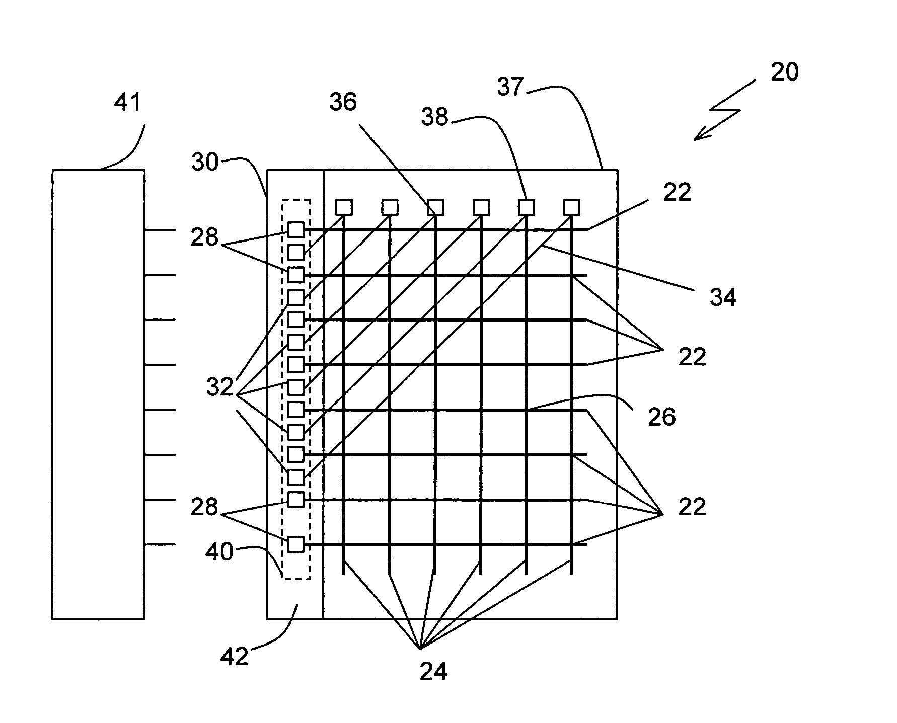
[0022] Electro-optic displays include a layer of electro-optic material, a term which is used herein in its conventional meaning in the art to refer to a material having first and second display states differing in at least one optical property, the material being changed from its first to its second display state by application of an electric field to the material. The optical property is typically color perceptible to the human eye, but may be another optical property, such as optical transmission, reflectance, luminescence or, in the case of displays intended for machine reading, pseudo-color in the sense of a change in reflectance of electromagnetic wavelengths outside the visible range.

[0023] The electro-optic displays in which the method of the present invention is used typically contain an electro-optic material which is a solid in the sense that the electro-optic material has solid external surfaces, although the material ...


PUM

PropertyMeasurementUnit
angleaaaaaaaaaa
angleaaaaaaaaaa
diametersaaaaaaaaaa

Abstract

An edge-addressable electronic display is provided including a row electrode in electric communication with a first termination and a column electrode in electric communication with a second termination. The row and column electrodes intersect at a pixel. Both the first and second terminations are disposed proximate to a first edge of the display, and as a result, the pixel may be addressed along the first edge of the display. The display may further include a removable driver circuitry for addressing the pixel in electric communication with at least one of the first and second terminations.

Description

CROSS-REFERENCE TO RELATED APPLICATIONS [0001] This application claims priority to and the benefit of U.S. Provisional Application Ser. No. 60 / 515,457 filed Oct. 29, 2003, the entire disclosure of which is incorporated herein by reference.FIELD OF THE INVENTION [0002] The present invention relates to electronic displays, and, more particularly, to nonemissive electro-optic displays addressable along one edge. BACKGROUND [0003] Electronic displays typically used today are rigid and frequently contain one or more sheets of rigid material. For example, liquid crystal displays have been traditionally manufactured by enclosing an optoelectrically active material between two pieces of breakable glass. These panel-type electronic display devices typically require a control circuit mounted on a rigid circuit board. For example, liquid crystal displays commonly used in laptop computers typically have several integrated circuits mounted on circuit boards arranged around the liquid crystal por...

Claims


Application Information

Patent Timeline
Patent Type & Authority Applications(United States)
IPC IPC(8): G02F1/155G02F1/167G09G3/34
CPCG02F1/155G02F2001/13456G02F1/167G02F1/13456
Inventor WILCOX, RUSSELL J.ALBERT, JONATHAN D.GATES, HOLLY G.
Owner E INK CORPORATION
Why Eureka
Try Eureka