
Vehicle headlight

a headlight and vehicle technology, applied in the direction of fixed installation, lighting and heating apparatus, lighting support devices, etc., can solve the problems of complicated structure of the lighting device, and achieve the effect of enhancing the ratio of utilizing the flux of light emitted from the light emitting element, and enhancing the accuracy of the positional relation between the projection lens and the rectilinear propagation blocking member

Active Publication Date: 2005-06-09
KOITO MFG CO LTD
View PDF9 Cites 47 Cited by
  • Summary
  • Abstract
  • Description
  • Claims
  • Application Information

AI Technical Summary

Benefits of technology

[0007] The present invention has been accomplished in view of the above circumstances. It is an object of the present invention to provide a vehicle headlight to form a predetermined light distribution pattern having a cutoff line at the upper end portion, when light is irradiated by a plurality of lighting device units, the vehicle headlight characterized in that: the thickness of the lighting device is reduced; and the optical axes of the plurality of lighting device units can be simultaneously adjusted without making the structure of the lighting device complicated.

Problems solved by technology

However, the above structure has the following problems.
Therefore, the lighting device structure becomes complicated.

Method used


Image

  • Vehicle headlight
  • Vehicle headlight
  • Vehicle headlight

Examples


Embodiment Construction

[0038] Referring to the drawings, an embodiment of the present invention will be explained below.

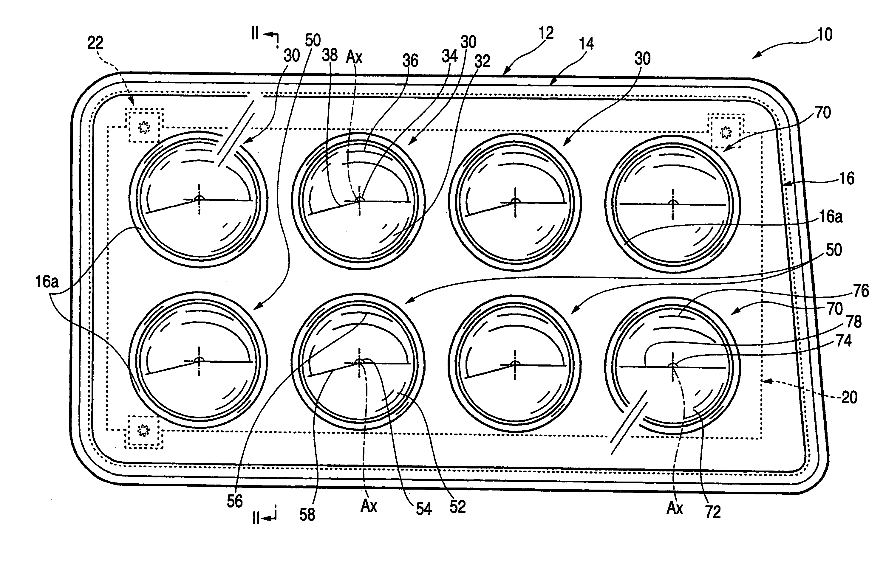
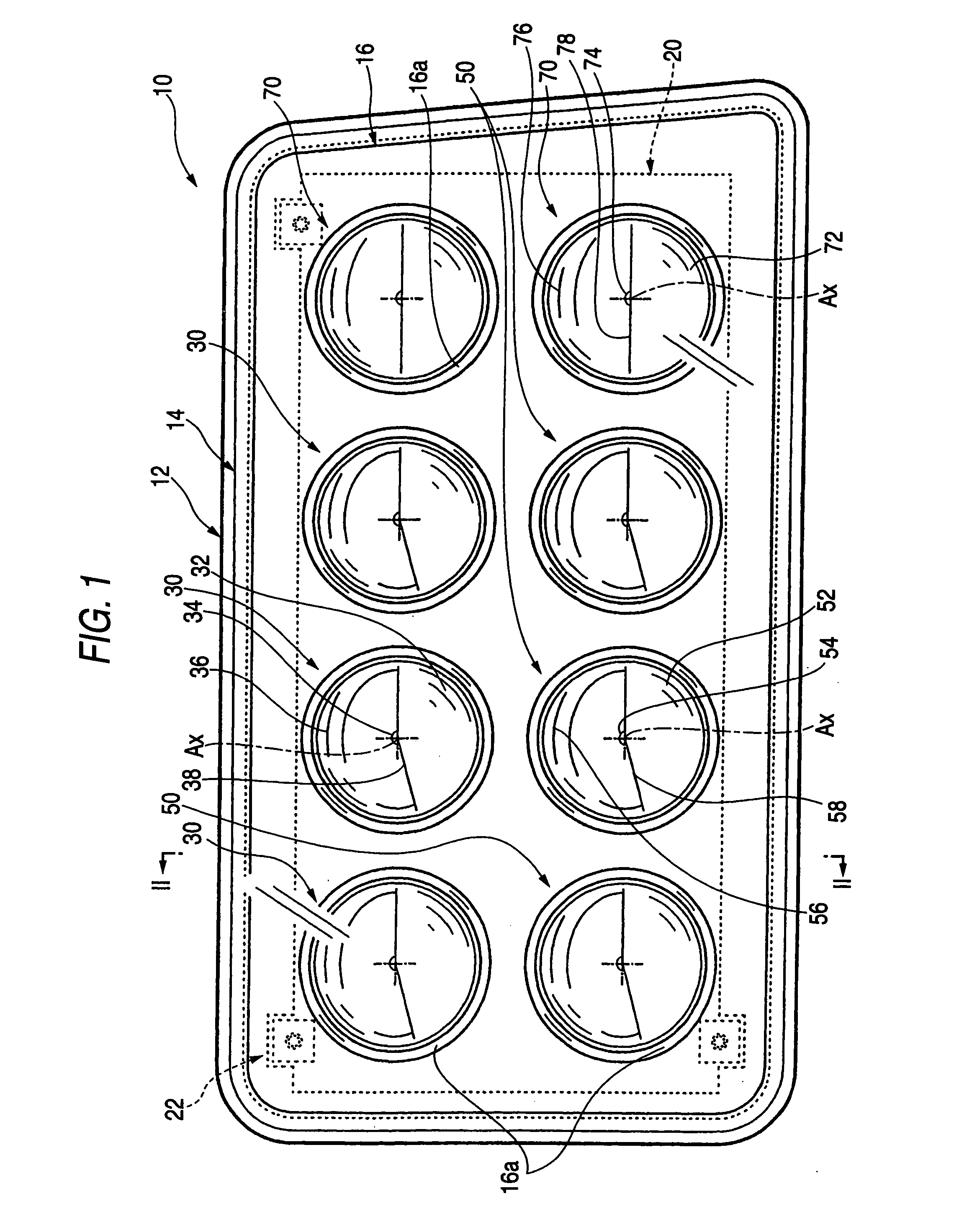
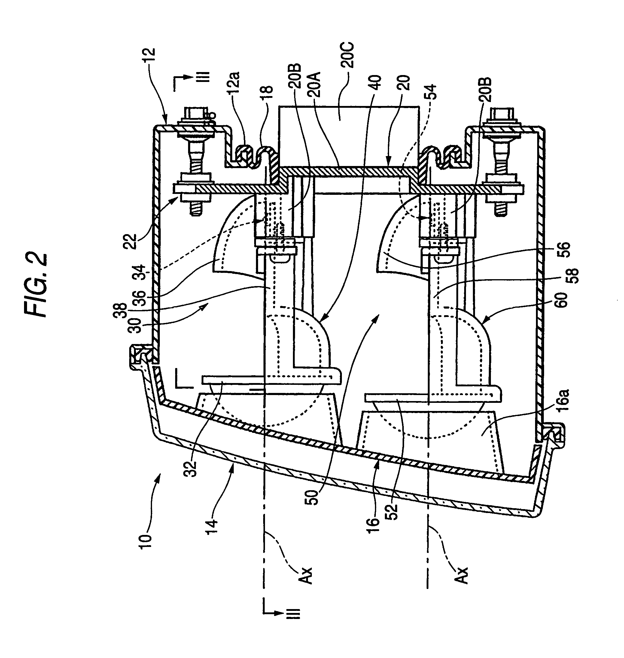
[0039]FIG. 1 is a front view showing a vehicle headlight of an embodiment of the present invention. FIG. 2 is a sectional view taken on line II-II in FIG. 1. FIG. 3 is a sectional view taken on line III-III in FIG. 2.

[0040] As shown in these drawings, the vehicle headlight 10 of this embodiment is a lighting device arranged on the right of a front end portion of a vehicle. The vehicle headlight 10 is composed in such a manner that eight lighting device units 30, 50, 70, four of them are arranged in the upper step and the other four of them are arranged in the lower step, are accommodated in a lighting chamber including a lamp body 12 and a transparent light transmission cover 14 attached to the front end opening of the lamp body 12. In this vehicle headlight 10, a light distribution pattern for a low beam can be formed by the irradiation of light sent from these eight lighting device u...


PUM


Abstract

A plurality of lighting device units 30, the light sources of which are light emitting elements 34, are tiltably supported by a common unit support member 20, so that optical axes of the plurality of lighting device units 30 are simultaneously adjusted. The projection lens 32 and the rectilinear propagation blocking member 38, which compose each lighting device unit 30, are integrated with each other as a light control member 40, and this light control member 40 and the light emitting element 34 are individually attached to the unit support member 20. Due to the foregoing, the lighting device structure can be made simple compared with the structure in which the completed lighting device unit is attached to the unit support member 20.

Description

BACKGROUND OF THE INVENTION [0001] The present invention relates to a vehicle headlight to form a predetermined light distribution pattern having a cutoff line at the upper end edge thereof, when light is irradiated by a plurality of lighting device units. [0002] In general, a vehicle headlight can form a light distribution pattern for a low beam having a cutoff line at the upper end edge. Due to the above constitution, while a driver in a vehicle running in the opposite direction is not being given glare, the front visibility in of a driver who drives a vehicle can be ensured as positively as possible. [0003] JP-A-2003-123517 discloses a vehicle headlight that forms a light distribution pattern for a low beam by the irradiation of light sent from a plurality of lighting device units having light emitting elements as the light sources. [0004] When the lighting device of JP-A-2003-123517 is employed, it becomes possible to reduce the thickness of the lighting device. However, in this...

Claims


Application Information

Patent Timeline
IPC IPC(8): B60Q1/06F21S8/10F21V11/00F21V11/16F21V14/02F21V17/00F21V19/00F21W101/10F21Y101/00
CPCB60Q1/06F21S48/1159F21Y2101/02F21S48/145F21S48/1163F21Y2115/10F21S41/147F21S41/155F21S41/43F21S41/151
Inventor WATANABE, SHIGEYUKITATARA, NAOKIOKUI, KAZUKIOHSHIO, HIROHIKOASHIZAWA, KAZUHISA
Owner KOITO MFG CO LTD
Learn More