Apparatus and method for heat-treatment of optical fiber reinforcing member and optical fiber fusion splicing apparatus
a technology of splicing apparatus and reinforcing member, which is applied in the direction of heater elements, instruments, optical elements, etc., can solve the problems of reducing affecting the heat capacity of the unit area, and affecting the cost and management of the reinforcing, so as to reduce the temperature difference between the contact part and the non-contact part and suppress the rise of the temperature of the non-contact part.
- Summary
- Abstract
- Description
- Claims
- Application Information
AI Technical Summary
Benefits of technology
Problems solved by technology
Method used
Image
Examples
first embodiment
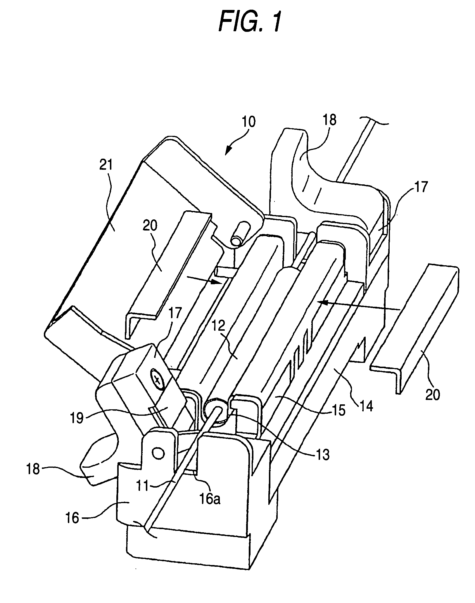
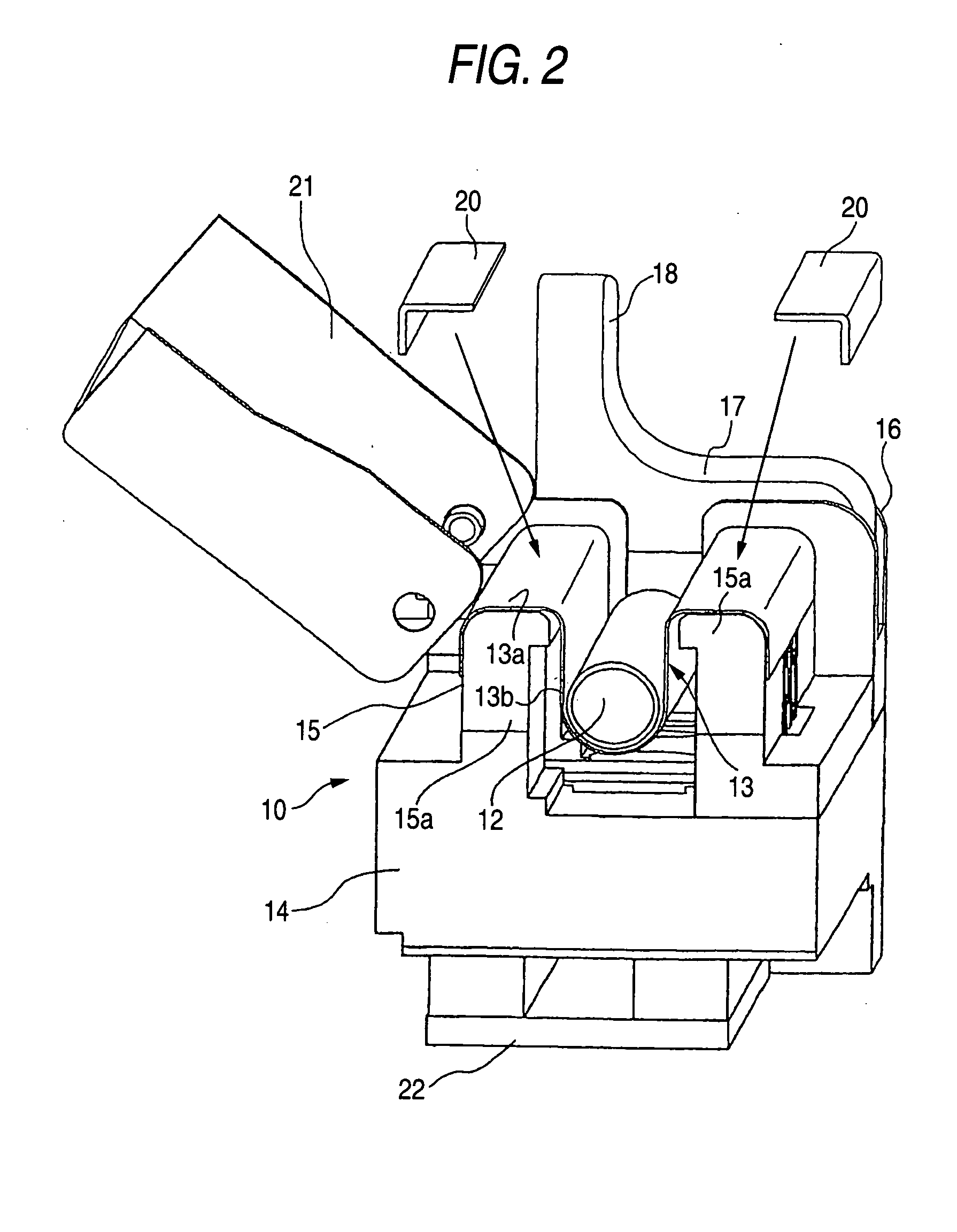
[0032]FIG. 1 is a view illustrating an apparatus for heat-treatment of an optical fiber reinforcing member according to the invention. FIG. 2 is a view illustrating a cross-sectional structure of the apparatus for heat-treatment, from which a part thereof shown in FIG. 1 is removed.
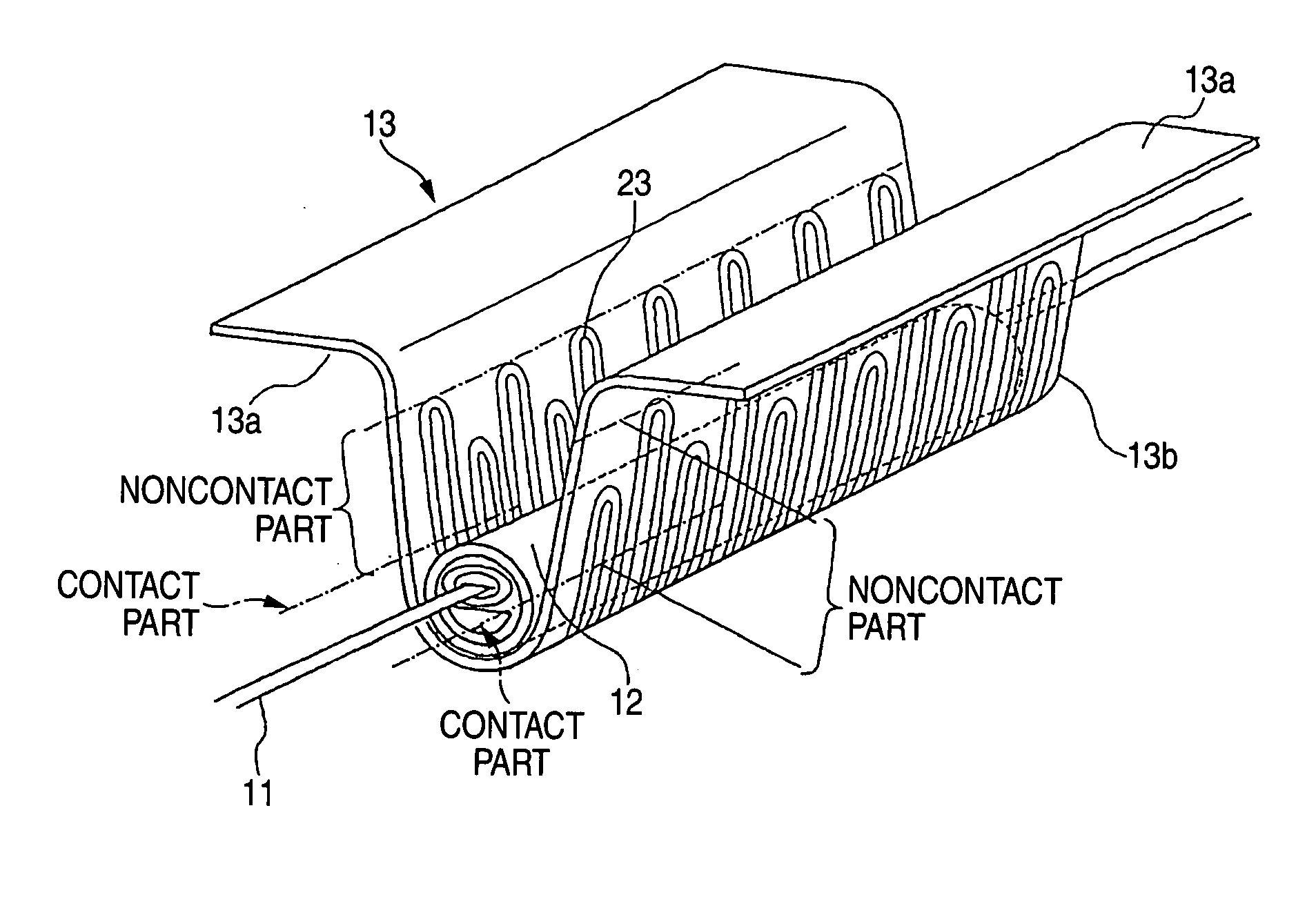
[0033] A heat-treatment apparatus 10 according to the first embodiment of the invention accommodates and supports a sheet-like heating body 13 for heating a reinforcing member 12 disposed in such a way as to protect fusion-spliced portion of single optical fibers or optical fiber ribbons 11 and the vicinity thereof. The reinforcing member 12 is constituted in such a manner as to accommodate a thermal melting tube, which is made of a hot melt adhesive resin, and a tensile strength member (referred to also as a reinforcing rod), which is made of a material, such as stainless steel, glass or ceramics, in a heat shrinkable tube, similarly to that shown in FIG. 15A. The sheet-like heating body 13 constituted b...
second embodiment
[0051] Next, the invention is described hereinbelow by referring to the drawings.
[0052]FIG. 6 is a view illustrating the second embodiment of an apparatus for heat-treatment of an optical fiber reinforcing member according to the invention. FIG. 7 is a view illustrating a cross-sectional structure of the apparatus for heat-treatment, from which a part thereof shown in FIG. 6 is removed.
[0053] As shown in FIGS. 6 and 7, a heat-treatment apparatus 110 according to the second embodiment of the invention has a sheet-like heating body 113, which has nonheating parts 113a and a heating part 113b, a base portion 14, a heating body supporting portion 15, which has supporting frames 15a, a clamp support 16, which has a groove portion 16a, a clamp piece 17, a lug portion 18, a grasping pad 19, pressure members 20, a cover 21, a circuit board 22, and a heat equalizing plate 125. Incidentally, members, which are the same as those of the heat-treatment apparatus 10 of the first embodiment of th...
PUM
 Abstract
Description
Claims
Application Information
 - R&D
- Intellectual Property
- Life Sciences
- Materials
- Tech Scout
- Unparalleled Data Quality
- Higher Quality Content
- 60% Fewer Hallucinations
Browse by: Latest US Patents, China's latest patents, Technical Efficacy Thesaurus, Application Domain, Technology Topic, Popular Technical Reports.
© 2025 PatSnap. All rights reserved.Legal|Privacy policy|Modern Slavery Act Transparency Statement|Sitemap|About US| Contact US: help@patsnap.com


