Method and apparatus for delivering targeted therapy to a patient

a targeted therapy and patient technology, applied in the field of targeted therapy delivery to a patient, can solve the problems of difficult control of radiation distribution to the target tissue, difficult to consistently achieve accurate catheter placement, and difficulty in delivering targeted therapy to patients

Inactive Publication Date: 2005-06-09
WASHINGTON UNIV IN SAINT LOUIS
View PDF9 Cites 127 Cited by
  • Summary
  • Abstract
  • Description
  • Claims
  • Application Information

AI Technical Summary

Benefits of technology

[0005] In yet another aspect, a method is provided of delivering targeted radiation brachytherapy to tissue adjacent a cavity of a patient using an applicator including a balloon having a deflated state in which the balloon is adapted for insertion into the cavity of the patient and an inflated state in which the balloon is enlarged for at least partially filling the cavity. The method includes attaching a catheter to the balloon for movement with the balloon, inserting the balloon and the catheter into the cavity when the balloon is in the deflated state, inserting a radiation source into the catheter so the radiation source is generally adjacent the balloon, inflating the balloon within the cavity so the radiation source is a predetermined distance from the tissue adjacent the cavity, and controlling a dose distribution of radiation delivered into the tissue adjacent the cavity by the radiation source by controlling the predetermined distance of the radiation source from the tissue.
[0006] In even another aspect, a method is provided of delivering targeted thermal therapy to tissue adjacent a cavity of a patient using an applicator including a balloon having a deflated state in which the balloon is adapted for insertion into the cavity of the patient and an inflated state in which the balloon is enlarged for at least partially filling the cavity. The method includes attaching a catheter to the balloon for movement with the balloon, inserting the balloon and the catheter into the cavity when the balloon is in the deflated state, inserting a heat source into the catheter so the heat source is generally adjacent the balloon, inflating the balloon within the cavity so the heat source is a predetermined distance from the tissue adjacent the cavity, and controlling a temperature increase of the tissue adjacent the cavity by controlling the predetermined distance of the heat source from the tissue.
[0007] In yet another aspect, the present invention includes an applicator system for facilitating the delivery of at least one of external beam radiation and external thermal therapy to tissue adjacent a cavity of a patient. The applicator system includes a balloon adapted for introduction to the cavity of the patient, wherein the balloon has a deflated state in which the balloon is adapted for insertion into the cavity and an inflated state in which the balloon is enlarged for at least partially filling the cavity of the patient. The balloon moves from the deflated state to the inflated state upon introduction of pressurized fluid to an interior of the balloon. The applicator system also includes a conduit in fluid communication with the interior of the balloon for introducing pressurized fluid to the interior of the balloon to move the balloon from the deflated state to the inflated state, and a catheter extending over at least a portion of the balloon. The catheter has a radio opaque maker therein adjacent the balloon for marking a position of the balloon when the balloon is received within the cavity.

Problems solved by technology

However, such free-hand placement is challenging and can vary greatly between operators, making it difficult to consistently achieve accurate placement of the catheter.
Moreover, a variety of organs are inaccessible for free-hand placement of brachytherapy catheters and therefore are not routinely treated with brachytherapy.
However, controlling the distribution of radiation to the target tissue as well as achieving a quick fall-off of dose to the non-target tissue can be difficult because of the single dwell position of the radiation source and because of the distance between the source and the target tissue.

Method used


Image

  • Method and apparatus for delivering targeted therapy to a patient
  • Method and apparatus for delivering targeted therapy to a patient
  • Method and apparatus for delivering targeted therapy to a patient

Examples


Embodiment Construction

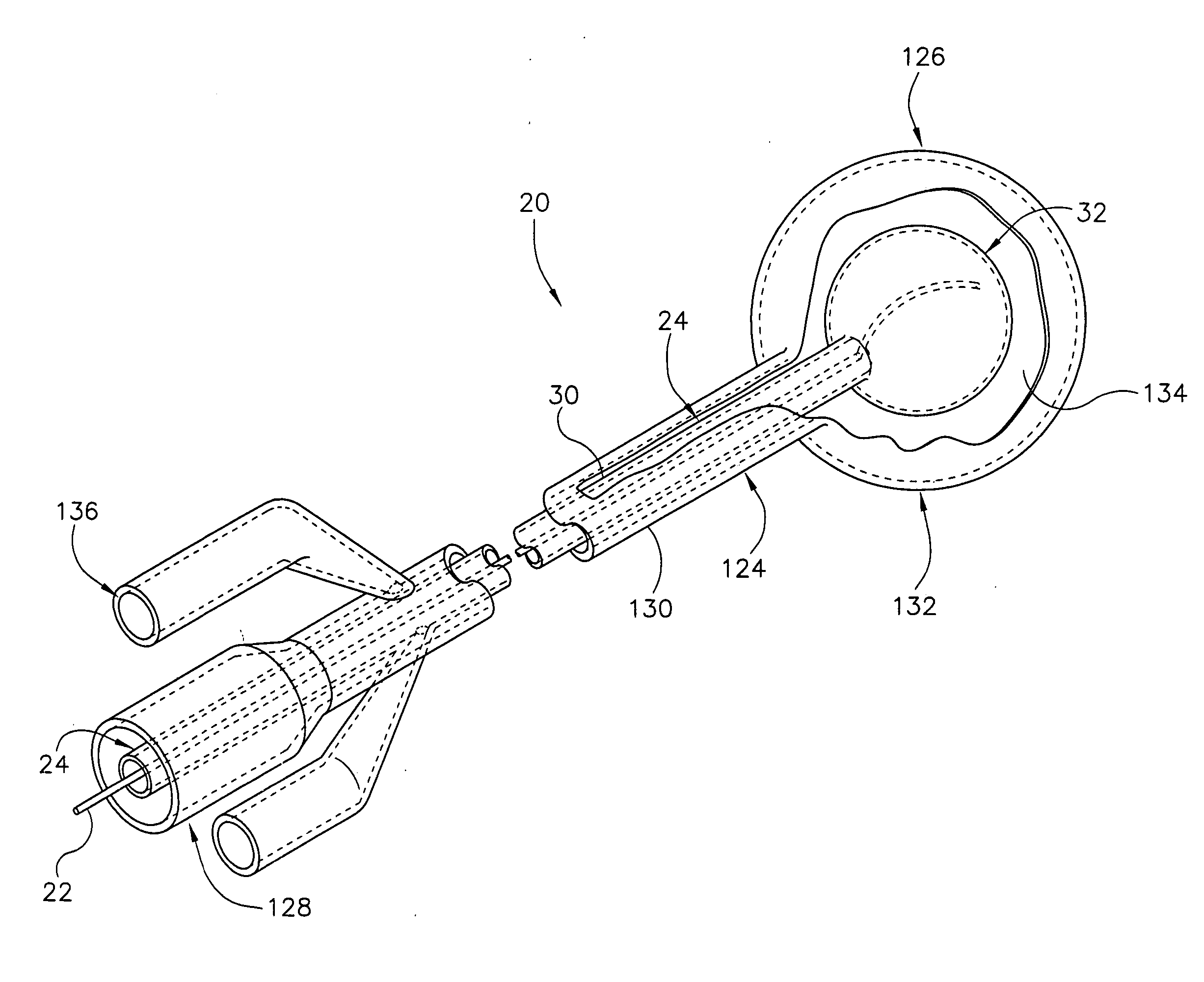
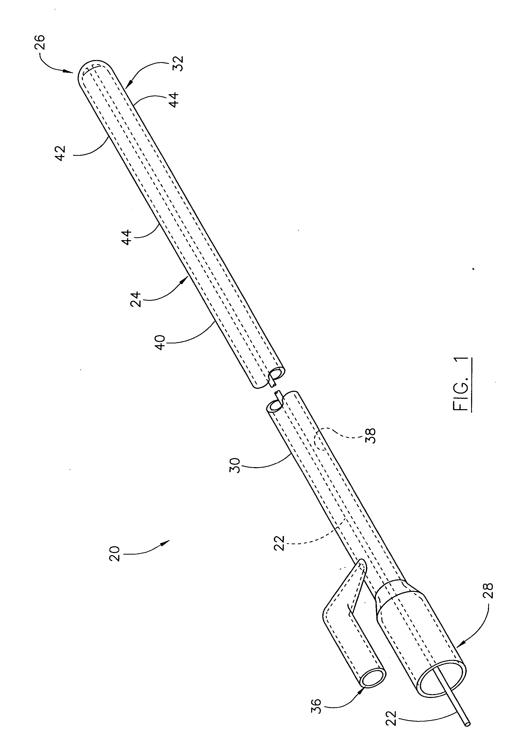
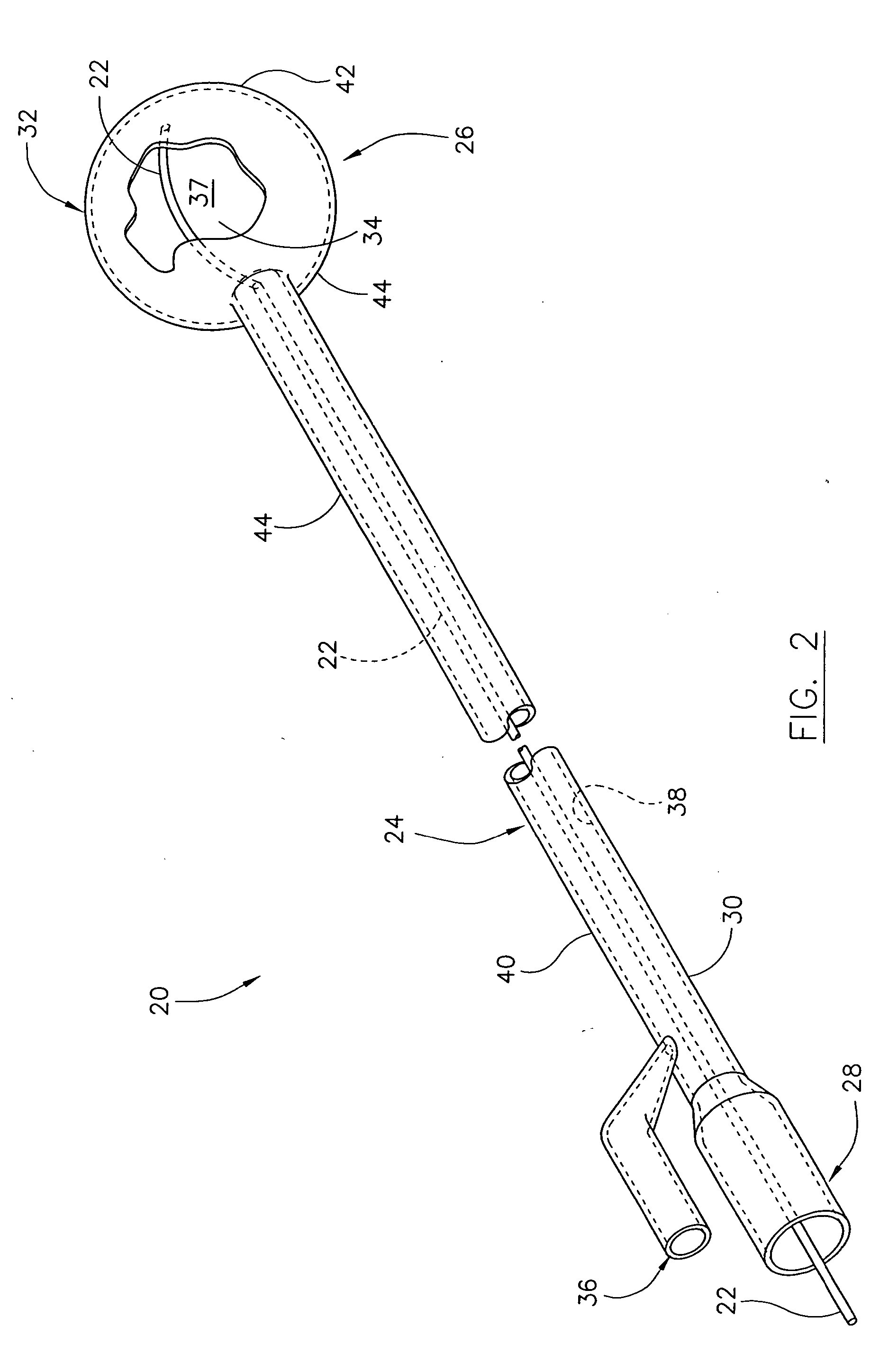
[0016] Referring now to the drawings, and more specifically to FIGS. 1 and 2, an applicator is designated in its entirety by the reference numeral 20. The applicator 20 includes a catheter 22 and a body (generally designated by 24) having a first end (generally designated by 26), a second end (generally designated by 28), a conduit 30 extending between the first end and the second end, and a balloon (generally designated by 32).

[0017] The balloon 32 is adapted for introduction to a cavity (designated by 62 in FIG. 3) of a patient, such as a patient's bladder, esophagus, and / or rectum. More specifically, the balloon 32 has a deflated state (FIG. 1) in which the balloon and the first end 26 of the body 24 are adapted for insertion into the cavity through an entrance to the cavity. Additionally, at least a portion of the conduit 30 may also be adapted for insertion through the entrance and into the cavity. The first end 26 of the body 24, the balloon 32 in its deflated state, and wher...


PUM


Abstract

An applicator for delivering targeted radiation brachytherapy to tissue adjacent a cavity of a patient. The applicator includes a balloon adapted for introduction to the cavity of the patient, wherein the balloon has a deflated state in which the balloon is adapted for insertion into the cavity and an inflated state in which the balloon is enlarged for at least partially filling the cavity of the patient. The balloon moves from the deflated state to the inflated state upon introduction of pressurized fluid to an interior of the balloon. The applicator also includes a conduit in fluid communication with the interior of the balloon for introducing pressurized fluid to the interior of the balloon to move the balloon from the deflated state to the inflated state, and a catheter extending over at least a portion of the balloon for delivering radiation from a radiation source to the tissue adjacent the cavity.

Description

BACKGROUND OF THE INVENTION [0001] The present invention relates generally to delivering targeted therapy to a patient, and more specifically to delivering targeted therapy to tissue adjacent a cavity of the patient. [0002] In radiation brachytherapy, catheters are placed in close proximity to the tissue targeted for radiation. Currently, such proximity is achieved by free-hand placement of brachytherapy catheters over a needle. However, such free-hand placement is challenging and can vary greatly between operators, making it difficult to consistently achieve accurate placement of the catheter. Moreover, a variety of organs are inaccessible for free-hand placement of brachytherapy catheters and therefore are not routinely treated with brachytherapy. Single balloon catheters have been used for brachytherapy to treat breast cancer using a radiation source positioned within the center of the balloon. However, controlling the distribution of radiation to the target tissue as well as ach...

Claims


Application Information

Patent Timeline
Patent Type & Authority Applications(United States)
IPC IPC(8): A61B18/18A61N5/04A61N5/10
CPCA61B18/18A61N2005/1018A61N5/1014A61N5/04
Inventor SINGH, ANURAG K.
Owner WASHINGTON UNIV IN SAINT LOUIS
Why Eureka
Try Eureka