Kneading massager

Inactive Publication Date: 2005-06-09
TSENG CHIN CHUN
View PDF4 Cites 18 Cited by
  • Summary
  • Abstract
  • Description
  • Claims
  • Application Information

AI Technical Summary

Benefits of technology

[0008] The main object of the present invention is to provide a kneading massager driven by a light and small sized

Problems solved by technology

However, employing an AC motor as its power source causes its overall structure heavy and bulky.
Besides, massaging the body with contact rollers can hardly bring a

Method used


Image

  • Kneading massager
  • Kneading massager
  • Kneading massager

Examples


Embodiment Construction

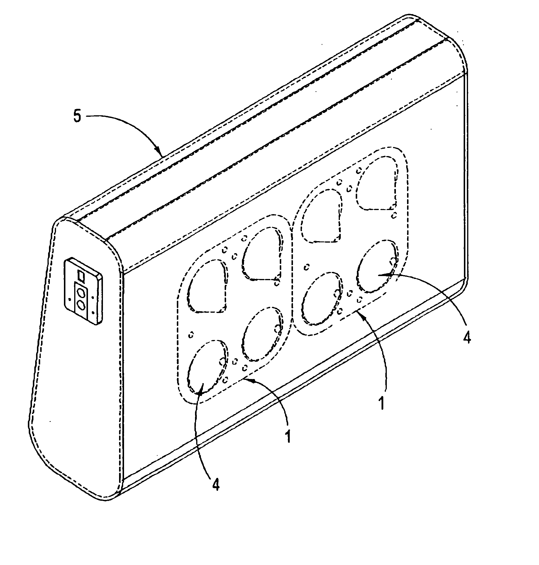
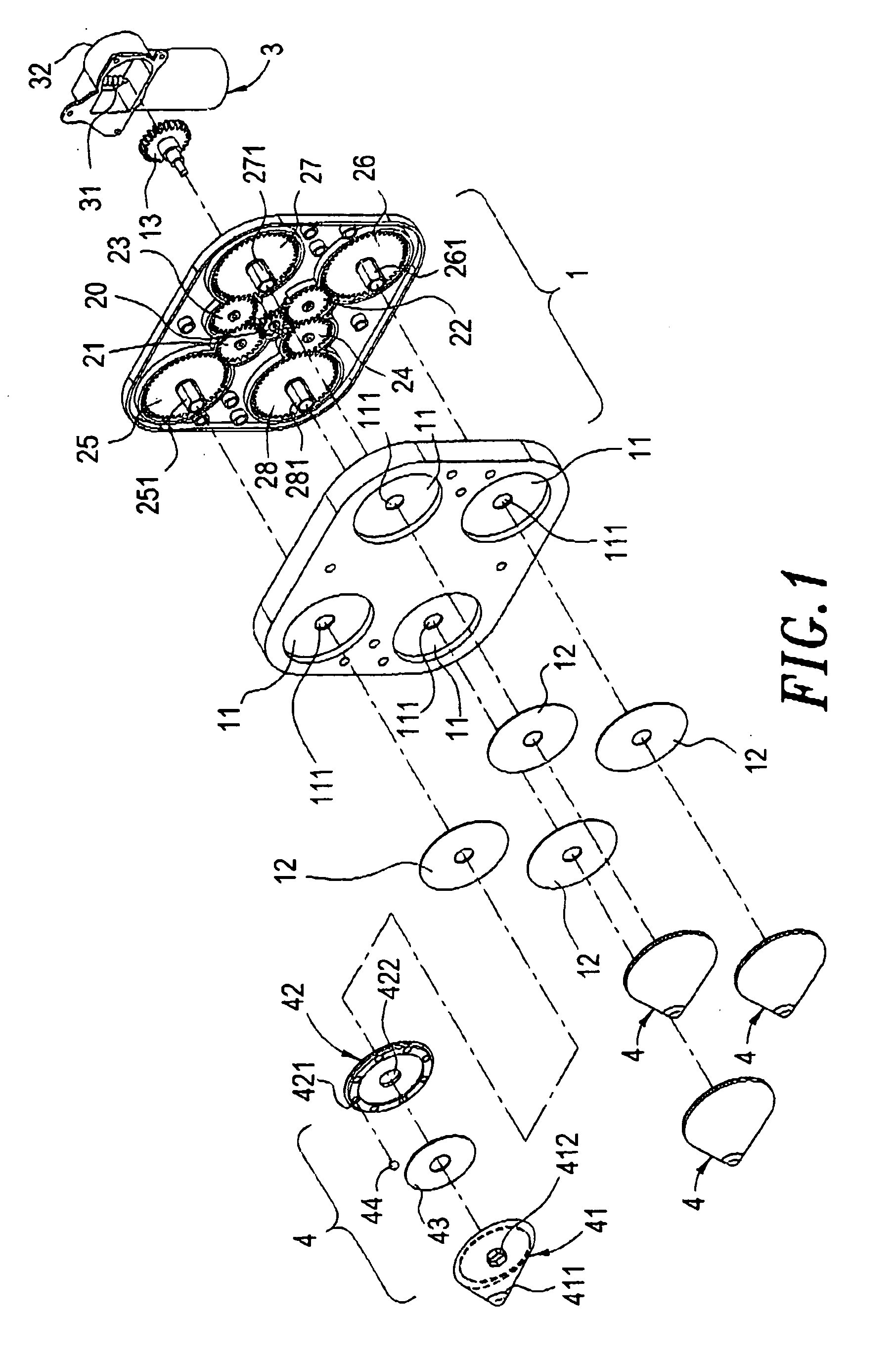
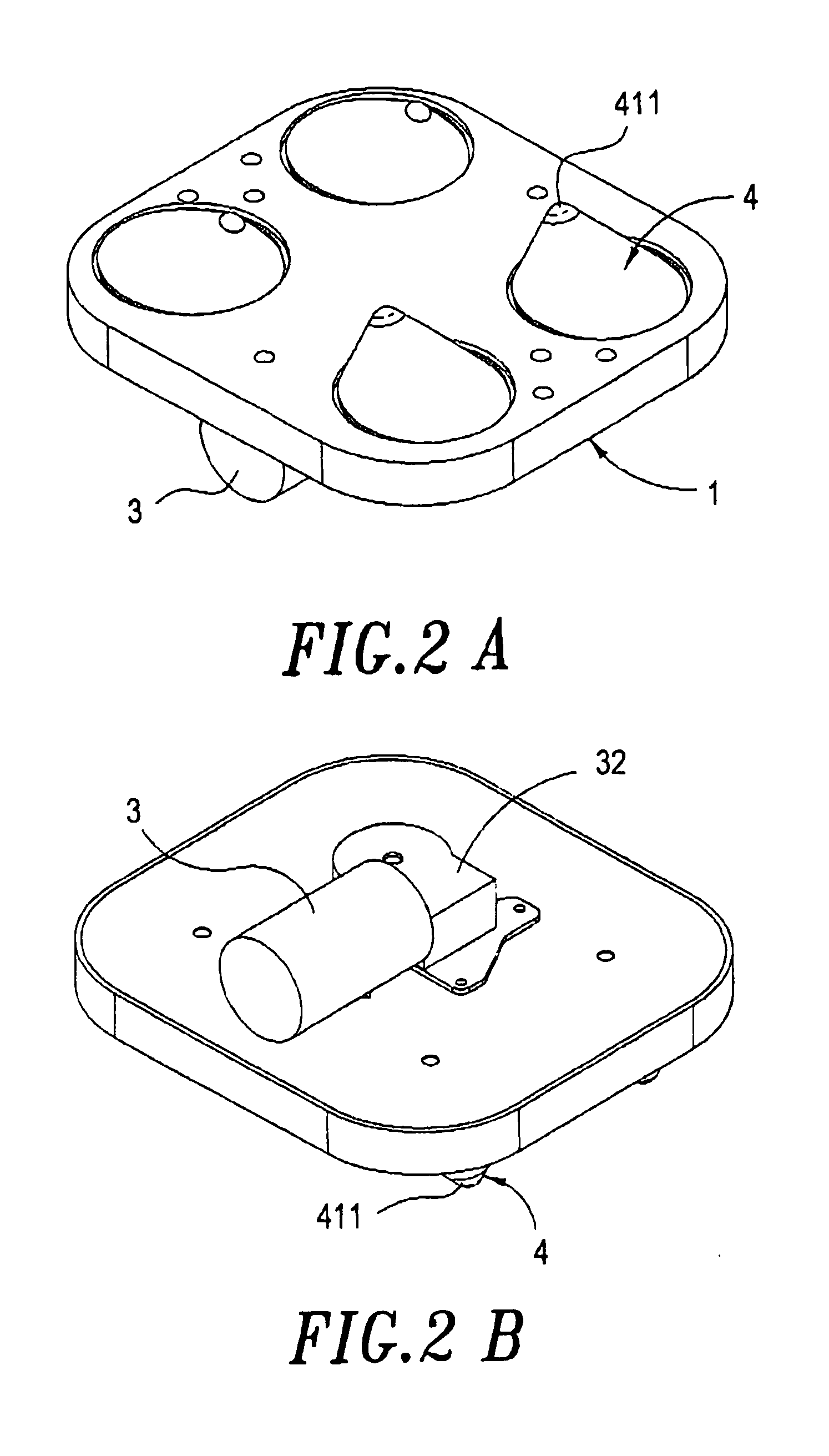
[0019] Referring to FIGS. 1, 2A and 2B simultaneously, the kneading massager of the present invention comprises a speed reduction gear unit 1, a DC motor 3, and a massage block 4. The speed reduction gear unit further includes a driver gear 20 and eight follower gears 21-28. The driver gear 20 is in mesh with the first and second follower gears 21, 22, whereas the first follower gear 21 is further in mesh with the third and fifth follower gears 23 and 25. The second follower gear 22 is in mesh with the fourth and sixth follower gears 24 and 26, whereas the seventh and eighth follower gears 27 and 28 are respectively in mesh with the third and fourth follower gears 23 and 24. As for the gear size the fifth to eighth follower gears 25-28 are the largest, while the first to fourth follower gears 21-24 rank to the next larger size, the driver gear 20 is the smallest. With such arrangement, the aforesaid gears are combined to form the speed reduction gear unit 1. The fifth to eight follo...


PUM


Abstract

A kneading massager has a speed reduction gear unit in mesh with the output shaft of a DC driving motor to input the mechanical power of the motor, the speed reduction gear unit has several output shafts to engage with a tapered massage block thereby making the massage block to perform tender and comfortable kneading motion like human fingers when being driven by the Dc motor.

Description

CROSS-REFERENCES TO RELATED APPLICATIONS [0001] The present invention is a Continuation-in-part (CIP) application of a pending non-provisional patent application with application No. 10 / 306,219 filed 29 Nov. 2002.BACKGROUND OF THE INVENTION [0002] 1. Field of the Invention [0003] The present invention relates to a kneading massager, and particularly, to a light, thin and small sized kneading massager capable of relaxing the user's muscle. [0004] 2. Description of the Prior Art [0005] As for the conventional massage chair, please refer to the Taiwan Bulletin No. 478359, “Massage Device for Massage chair (cited Reference). It mainly includes the following components: a base plate that has a top forming a rail level and a set block provided respectively at both ends of the plate; each of the set blocks has a hinge hole and a screw bolt whose two ends being hinged to the hinge holes, the one end thereof is connected to a power source so that the screw bolt is able to rotate between the ...

Claims


Application Information

Patent Timeline
IPC IPC(8): A61H7/00A61H37/00
CPCA61H2201/1669A61H7/004A61H7/007A61H2201/0134A61H2201/0142A61H2201/0149A61H2201/1207A61H2201/1463A61H2201/1671
Inventor TSENG, CHIN-CHUN
Owner TSENG CHIN CHUN
Why Eureka
Try Eureka